
Водонагреватели TESY GCV6S 804724D C21 TS2RCP 303560 - инструкция пользователя по применению, эксплуатации и установке на русском языке. Мы надеемся, она поможет вам решить возникшие у вас вопросы при эксплуатации техники.
Если остались вопросы, задайте их в комментариях после инструкции.
"Загружаем инструкцию", означает, что нужно подождать пока файл загрузится и можно будет его читать онлайн. Некоторые инструкции очень большие и время их появления зависит от вашей скорости интернета.


8
Instructions for use and maintenance
EN
•
the phase - to mark A, A1, L or L1;
•
the neutral - to N (B or B1 or N1)
•
The safety wire must be obligatory connected to the screw joint marked with
After the installation, put the plastic cover back in its place!
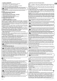
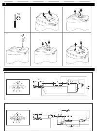
Explanations to Fig. 3:
T2 - thermal switch; T1 - thermal regulator; S - switch; R - heater; SL1, SL2, SL3 - light indicator;
F - flange
.
V.
RUST PROTECTION MAGNESIUM ANODE
The magnesium anode protects the water tank’s inner surface from corrosion.
The anode element is an element undergoing wear and tear and is subject to
periodic replacement.
In view of the long-term and accident free use of your water heater, the
manufacturer recommends periodic inspections of the magnesium anode’s
condition by a qualified technician and replacement whenever required, and this
could be performed during the appliance’s technical preventive maintenance.
For replacements, please contact the authorized service stations!
VI.
OPERATION
1.
Switch on:
Before switching on the appliance for first time, make sure that the water heater is
properly connected to the power supply network and full with water.
The appliance is switched on by a switch integrated into the installation, described
in item 3.3 of Section IV, or upon connecting the plug to the electrical contact (in
the case of an extension cable with plug).
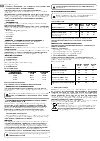
2.
Water heaters with electromechanical control
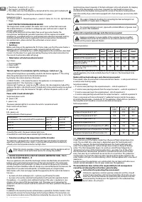
Fig. 2 shows:
1 - Thermal regulator
2 - Power switch
3 - Indicator lights
Thermal regulator (1) and indicator light for „heating up / ready to use“
Setting of the temperature is provided by a knob for the thermal regulator (1). This setting
allows for gradual adjustment to the desired temperature.
Fig.2 displays the rotation direction of the knobs.
e ENERGY SAVING – in this mode the water in the appliance is at a temperature of
approximately 60°С. Thus thermal loss is reduced.
Indicator light “heating up / ready to use“
- indicates the status/operation mode of the
appliance: the light is red while the water is heated and it is blue when the water has reached
the temperature as set by the thermostat. The light is off when the power switch is in off
position.
Power switch (2) and indicator lights
Single-level power switch:
0
– power is off;
I
– power is on;
The power indicator light for
I
is on when the switch is turned on at level
I
.
Power switch with two levels:
0
– power is off;
I, II
– power is on;
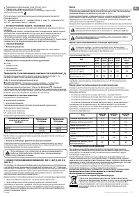
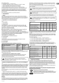
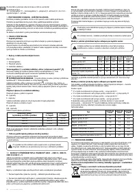
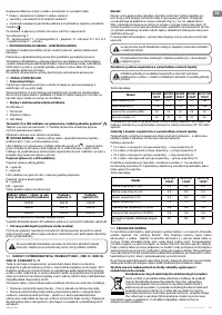
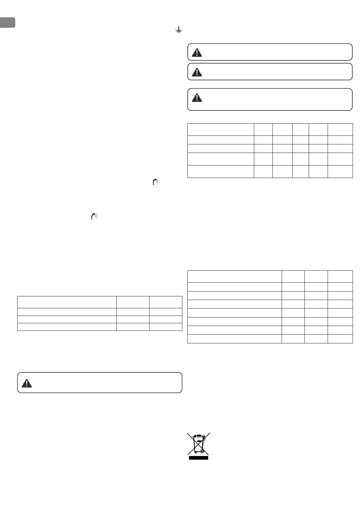
Selection of levels of heating power:
Rated power
(as marked on the nameplate of the appliance )
Switched to
level (
I
)
Switched to
level (
II
)
1200 W
600 W
1200 W
1600 W
800 W
1600 W
2400 W
1200 W
2400 W
At level
I
of the switch, the power indicator light
I
is on.
At level
II
of the switch both power indicator lights
I
and
II
are on.
3.
Protection according to the temperature (valid for all models)
The appliance is equipped with a special facility (thermal circuit-breaker) for protection
against over-heating of the water, which is switching off the heater from the electricity
network, when the temperature reaches too high values.
When this device operates, it does not self-reset and the appliance will not
work. Please call an authorized service for solving the problem.
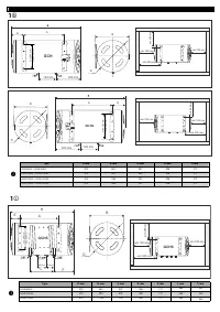
VII.
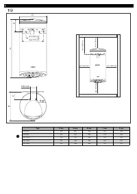
MODELS EQUIPPED WITH A HEAT EXCHANGER (SERPENTINE TUBE) - FIG.1C,
FIG.1D, FIG.1E AND TABLES
3 ÷ 5
These are appliances with inbuilt heat exchanger and are intended to be connected to the
heating system with maximum temperature of the heat carrier of 80°C. The control over
the flow through the heat exchanger is a matter of solution for the particular installation,
whereby the choice should be made at its design (e.g. external thermostat that measures the
temperature in the water tank and operates a circulation pump or a magnet valve).
Water heaters with a heat exchanger provide the opportunity for the water to be heated in
two ways:
1.
by means of a heat exchanger (coil) – a primary way of heating the water,
2.
by means of an auxiliary electrical heating element with automatic operation, built in
the appliance – it is used only when additional heating of the water is needed or in case
of repairs to the system of the heat exchanger (coil). The proper way of connecting the
appliance to the electric network and how to work with it has been specified in the previous
paragraphs.
Mounting
In addition to the mounting manner outlined above, especially for the latter models, it shall
be required to connect the heat exchanger to the heating installation. The connections are
to be carried out in observance of the direction indicated by the arrows on Fig. 1c, 1d, 1e. We
recommend you mount stopcocks at the heat exchanger’s entry and exit points. By stopping
the flow of the thermophore via the lower (stopcock) you shall avoid the unnecessary
circulation of the thermophore during periods of use only of the electric heating element.
Upon disassembly of you water heater equipped with a heat exchanger you must close both
stopcocks.
The usage of dielectric bushings for connecting the heat exchanger to an
installation of copper pipes is obligatory.
For ensuring minimal corrosion, pipes with a limited diffusion of gasses must
be used in the installation.
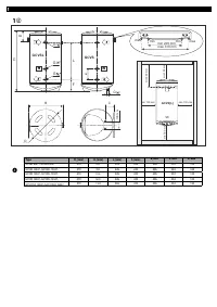
Models with a single heat exchanger and a thermal sensor pocket
Appliance installation is responsibility of the customer hence a qualified
installation technician has to perform it in accordance with the main user
guide and the present appendix thereto.
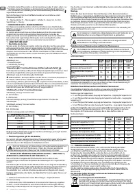
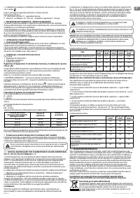
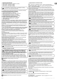
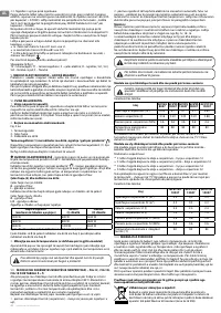
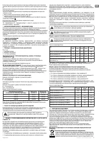
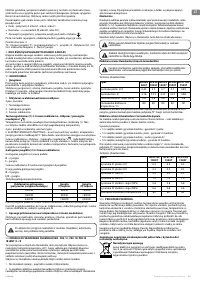
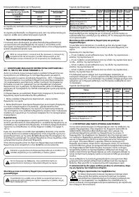
Technical parameters:
Type
GCV6S
8047
GCV9S
10047
GCV9S
12047
GCV9S
15047
GCV11SO
15047
Surface of the serpentine (m²)
0.45
0.7
0.7
0.7
0.83
Volume of the serpentine (l)
2.16
3.23
3.23
3.23
3.88
Operational pressure of the
serpentine (MPa)
0.6
0.6
0.6
0.6
0.6
Maximum temperature of the
heat carrier (°C)
80
80
80
80
80
For models with a possibility for installation of the thermal sensor pocket, delivered along
with the appliance, it has to be installed where the „TS“ lead-in is. The thread needs to be
tightened.
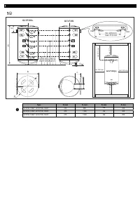
Models with two heat exchangers and a thermal sensor pocket
These models allow for connection to two external heat sources – a solar panel and local
or central water heating supply.
Serpentine markings:
•
S1 and an arrow pointing at the serpentine lead-in – inlet of serpentine S1
•
S1 and an arrow pointing outwards from the serpentine lead-in – outlet of serpentine S1
•
S2 and an arrow pointing at the serpentine lead – inlet of serpentine S2
•
S2 and an arrow pointing outwards from the serpentine lead-in – outlet of serpentine S2
There is a connexion with internal thread of ½” welded to the water tank for the purposes
of installing thermal probe – marked with ‘TS”. The appliance is fitted with brass pocket for a
thermal probe which should be screwed into the aforesaid connexion.
Technical parameters:
Type
GCV7/4S
10047
GCV7/4S
12047
GCV7/4S
15047
Surface of serpentine S1 (m²)
0.5
0.5
0.5
Surface of serpentine S2 (m²)
0.3
0.3
0.3
Volume of serpentine S1 (l)
2.4
2.4
2.4
Volume of serpentine S2 (l)
1.4
1.4
1.4
Operational pressure of serpentine S1 (MPa)
0.6
0.6
0.6
Operational pressure of serpentine S2 (MPa)
0.6
0.6
0.6
Maximum temperature of heat carrier (°C)
80
80
80
VIII.
PERIODIC MAINTENANCE
Under normal use of the heater, under the influence of high temperature, lime
scale /the so-called lime scale layer/ is deposited upon the heating element’s
surface. This worsens the heat exchange between the heating element and
water. The heating element’s surface temperature increases along /of boiling
water/. The thermoregulator begins to switch on and off more frequently. A
‘’deceptive” activation of the thermal protection is possible. Due to these facts,
the manufacturer recommends preventive maintenance of your water heater
every two years by an authorized service center or service base. This protective
maintenance must include cleaning and inspection of the anode protector (for
water heaters with glass-ceramic coating), which shall be replace with a new one if
need arises.
In order to clean the appliances use a damp cloth. Do not clean with abrasive or
solvent content detergents. Do not pour water over the appliance.
The manufacturer does not bare the responsibility for all consequences
caused by not obeying the instructions, given hereby.
Instructions for protecting the environment
Old electric appliances contain precious materials and thus should
not be thrown together with the household litter. We kindly ask you
make your active contribution for protecting the resources and the
environment by handing over the appliance in the authorized buy-
back stations (if such exist).

