Водонагреватели Tesy GCU 1520 - инструкция пользователя по применению, эксплуатации и установке на русском языке. Мы надеемся, она поможет вам решить возникшие у вас вопросы при эксплуатации техники.
Если остались вопросы, задайте их в комментариях после инструкции.
"Загружаем инструкцию", означает, что нужно подождать пока файл загрузится и можно будет его читать онлайн. Некоторые инструкции очень большие и время их появления зависит от вашей скорости интернета.


Instructions for use and maintenance
9
EN
English
II.
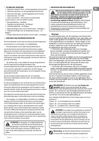
TECHNICAL SPECIFICATIONS
1.
Nominal volume V, liters - see the appliance's rating plate
2.
Nominal voltage - see the appliance's rating plate
3.
Nominal power consumption - see the appliance's
rating plate
4.
Nominal pressure - see the appliance's rating plate
ATTENTION! This is not the water mains pressure. This
is the pressure that is announced for the appliance and
refers to the requirements of the safety standards.
5.
Water heater type - closed accumulating water heater,
with thermal insulation
6.
Inner coating: GC-glass-ceramics
7.
Daily energy consumption – see Annex I
8.
Rated load profile - see Annex I
9.
Quantity of mixed water at 40°C V40 litres - see Annex I
10.
Maximum temperature of the thermostat - see Annex I
11.
Default temperature settings - see Annex I
12.
Energy efficiency during water heating - see Annex I
III.
DESCRIPTION AND PRINCIPLE OF OPERATION
The appliance is designed to operate in regions where the
water hardness is not more than 10°dH. In case that it is
installed in a region where the water is harder it is possible
that limestone precipitation accumulate very fast. This
can cause a specific noise during heating, as well as fast
damaging of the electrical part. For regions with harder
water yearly cleaning of the limestone precipitation in the
appliance is recommended, as well as usage of not more
than 2 kW of heating power
The appliance consists of a body, flange, plastic control
panel, safety return valve.
1.
The body consists of a steel reservoir (water tank) and
plastic housing (outer shell) with thermal insulation placed
in-between, and two pipes with thread G ½“, for cold water
supply (marked with a blue ring) and hot water discharge
(marked with a red ring). The inner reservoir is made of steel
proved against corrosion by a special glass-ceramic coating
2.
The flange is fitted with electric heater and magnesium
anode protector. The flange is fixed to the water tank with
bolts.
The electric heater heats the water in the tank and is
controlled by the thermostat, which automatically maintains
the preset temperature.
The plastic control panel incorporates: switch (depending on
model), adjustable thermostat (depending on model), and
thermal cut-out and control lamps.
The thermal cut-out is a device, which switches the heater
off the power supply when the water temperature reaches
excessive values. If this device is actuated, you should call a
service station.
The signal lamps (depending on model) on the control panel
indicate the current mode of the unit.
The magnesium protector provides additional anti-corrosion
protection to the internal tank for heaters fitted with glass-
ceramic coating.
3.
The safety-return valve prevents the appliance's complete
emptying in the event of cold water supply interruption.
The valve protects the appliance from pressure increases
higher than the allowed value during heating (! pressure
will increase when temperature increases), by releasing the
excess pressure through the drain outlet. Water dropping
out through the drains during the warming process is a
normal event that must be taken into consideration when
the boiler is installed.
ATTENTION! The safety-return valve cannot protect the
appliance in the event of water mains pressure in excess
of the acceptable pressure stated for the appliance.
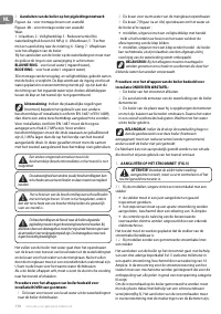
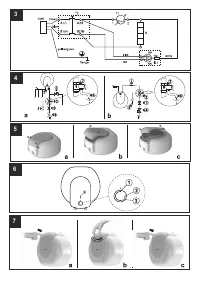
IV.
INSTALLATION AND SWITCH ON
Attention! Improper installation and connection of the
appliance may make it hazardous for the health and life of
consumers. It may cause grievous and permanent
consequences, including but not limited to physical injuries and/or
death. Improper installation and connection of the appliance may
also lead to damage to the consumers’ property /damage and/ or
destruction/, or to that of third persons, as a result of, but not
limited to flooding, explosion and/or fire.
Installation, connection to the main water and power supply, and
putting into operation must be carried out by certified electricians
and technical personnel certified in installation of this category of
appliances, who have obtained their license in the state where the
installation and commissioning of the appliance are carried out,
and in compliance with its local legislation.
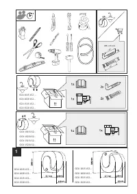
1.
Installation
We recommend installation of the device at close
proximity to locations where hot water is used, in order
to reduce heat losses during water transportation. The
selected location must exclude the possibility of water
spray originating from the showerhead or other water
contacts.
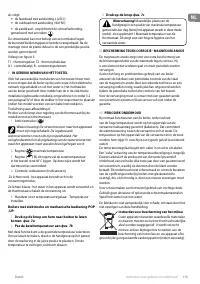
•
Appliances designed for installation
above sinks
are
assembled in such a manner that the outlet/inlet pipes are
pointed downwards (to the floor of the premise).
The appliance is affixed to a wall by means of mounting
brackets attached to the unit's body. Two hooks are used
to fix the appliance (min. Ø 4 mm) firmly on the wall
(included in the mounting set).
•
Appliances designed for installation
under sinks
are
assembled in such a manner that the outlet/inlet pipes are
pointed upwards (to the ceiling of the premise).
The appliances can be placed standing on the floor or
mounted on the wall.
In case you want to mount the appliance on the wall, the
suspension must be done with two hooks (min. Ø 4 mm)
securely attached to the wall.
IMPORTANT: The type of appliance designed to be
installed UNDER / ABOVE a sink is marked on the
appliance.
The bearing plank construction for boilers installed above
/ under sinks is universal and allows the space between
hooks to vary between 96 and 114mm. (fig.2).
For clear understanding of wall installation schemes, please
refer to fig.2 (A above sink, B under sink and C for floor
installation).
Характеристики

Остались вопросы?Не нашли свой ответ в руководстве или возникли другие проблемы? Задайте свой вопрос в форме ниже с подробным описанием вашей ситуации, чтобы другие люди и специалисты смогли дать на него ответ. Если вы знаете как решить проблему другого человека, пожалуйста, подскажите ему :)
