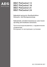
Водонагреватели AEG DDLT PinControl 13 / 18 / 21 / 24 - инструкция пользователя по применению, эксплуатации и установке на русском языке. Мы надеемся, она поможет вам решить возникшие у вас вопросы при эксплуатации техники.
Если остались вопросы, задайте их в комментариях после инструкции.
"Загружаем инструкцию", означает, что нужно подождать пока файл загрузится и можно будет его читать онлайн. Некоторые инструкции очень большие и время их появления зависит от вашей скорости интернета.


28
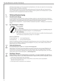
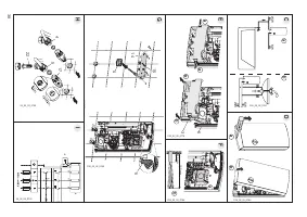
For contractors
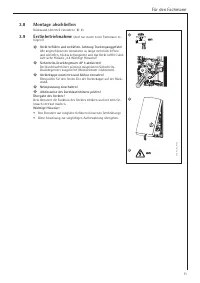
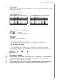
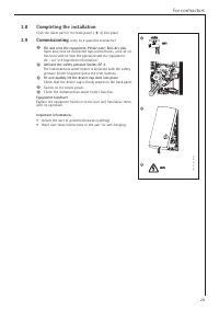
3.1
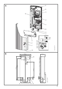
General installation information
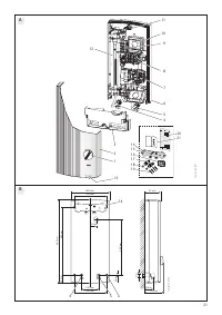
At the factory, the device is prepared for a power connection from the top from an installation below
the plaster (see Fig.
C
-
I
):
• Thedeviceissuitableforaboveorundersinkinstallation
C
.
• Waterconnection-threadedittingsbelowtheplaster.
• Powerconnectionbelowtheplasterintheupperdevicearea.
3.2
Installation site
Installtheinstantaneouswaterheateraccordingtotheigure
C
(a-oversink or b-undersink) vertically, flush
with the wall and in a room free from the risk of frost.
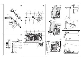
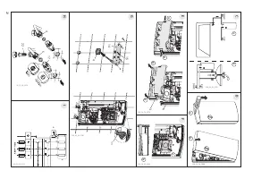
3.3
Preparing the device installation
• Openthedevice
D
:
a
Disengage the locking device with a screwdriver.
b
Open and remove the device cap.
• Removethelowerpartofthebackpanel
E
:
a
Push in both locking hooks.
b
Remove the lower part of the back panel towards the front.
• Breakoutthecablegrommetknock-outinthebackpanel
(
F
a). If the wrong knock-out has been
opened by mistake, a new back panel must be used.
• Trimthepowercabletosize
(
F
b).
• Removetheprotectivetransportplugsfromthewaterconnections
.
3.4
Fitting the mounting bracket
G
• Markouttheholestobedrilledusingtheinstallationtemplatesupplied(existing/suitableAEGmounting
bracket can be used).
• Securethemountingbracketwith2screwsandrawlplugs(notpartofthestandarddelivery;selectin
accordancewiththematerialoftheixingwall).
• Insertthestudssuppliedintothemountingbracket.
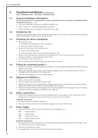
3.5
Equipment installation
G
•
Seal in and insert the twin nipples.
• Pushthecablegrommet(4)overthepowercable.
• Slidethebackpaneloverthestudsandthecablegrommet,pullthecablegrommetwithapairofpliers
against the locking hooks and let both hooks audibly click into place.
• Pushthebackpanelirmlyandlushagainstthewallandlockwiththeixingtoggle(11).Atthebottom,
the device can be secured with 2 additional screws (
M
19).
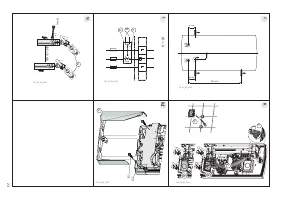
3.6
Water connection
H
•
Position the threaded connections with flat packing onto the twin nipples; for this observe the correct
seating of the connections (never twist the bayonet closures inside the device).
Important information
:
•
Thoroughly flush the cold water supply line.
•
Never use the shut-off valve in the cold water supply (17) to reduce the flow rate.
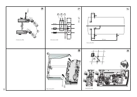
3.7
Power supply
• Connectthepowercabletotheterminalstrip(seewiringdiagram
I
).
BHZ
= Heating system
MS
= Micro switch
MRF
= Output switch unit
AP3
= Safety pressure limiter
Important information
:
• TheprotectionlevelIP25(hoseproof)isonlyassuredifthecablegrommetisittedcorrectly(
G
or
K
)
and if the cable sheath is sealed correctly.
•
Connect the equipment to earth.
•
For supply cables > 6 mm², increase the hole in the cable grommet.
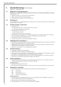
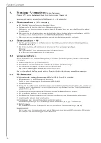
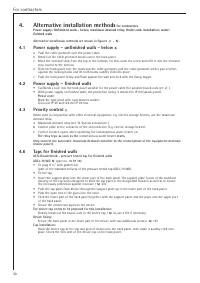
3.
Standard installation
for contractors
Power: Unfinished walls - top; Water: Unfinished walls
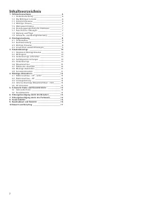
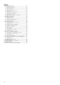
Содержание
- 36 Оглавление
- 40 Для пользователя и специалиста; Описание устройства; Указания по технике безопасности; Руководство по применению
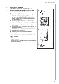
- 41 Продуктивность нагрева горячей воды; Первая помощь при неполадках; Руководство по применению и монтажу
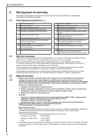
- 42 Конструкция устройства; Для специалиста; Инструкция по монтажу
- 43 Предписания и нормы
- 44 Стандартный монтаж
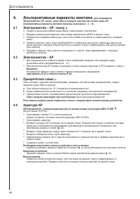
- 46 Электромонтаж – UP - внизу; Альтернативные варианты монтажа
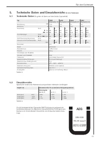
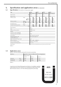
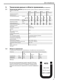
- 47 Технические данные и области применения; Технические данные
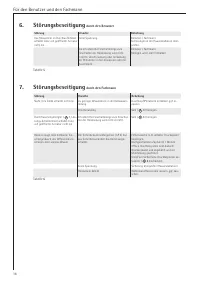
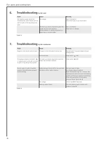
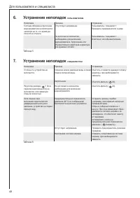
- 48 Устранение неполадок
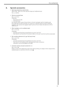
- 49 Специальные принадлежности
- 50 Сервисная служба и гарантия; Гарантия


