
Шуруповерты Ryobi ONE+ LCDI1802M - инструкция пользователя по применению, эксплуатации и установке на русском языке. Мы надеемся, она поможет вам решить возникшие у вас вопросы при эксплуатации техники.
Если остались вопросы, задайте их в комментариях после инструкции.
"Загружаем инструкцию", означает, что нужно подождать пока файл загрузится и можно будет его читать онлайн. Некоторые инструкции очень большие и время их появления зависит от вашей скорости интернета.


4
English
GB
FR
DE
ES
IT
NL
PT
DK
SE
FI
NO
RU
PL
CZ
HU
RO
LV
LT
EE
HR
SI
SK
GR
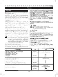
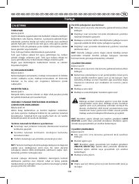
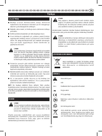
TR
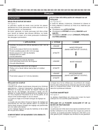
OPERATION
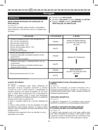
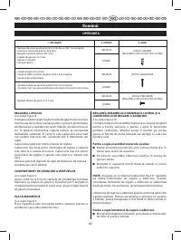
TORQUE ADJUSTMENT
See Figure 8.
When using the drill-driver for various driving applications,
it becomes necessary to increase or decrease the torque
in order to help prevent the possibility of damaging
screw heads, threads, workpiece, etc. In general, torque
intensity should correspond to the screw diameter. If the
torque is too high or the screws too small, the screws
may be damaged or broken.
The torque is adjusted by rotating the torque adjustment ring.
The torque is greater when the torque adjustment ring
is set on a higher setting. The torque is less when the
torque adjustment ring is set on a lower setting.
The proper setting depends on the type of material and
the size of screw you are using.
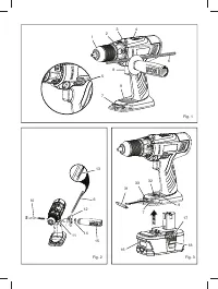
BIT STORAGE
See Figure 3.
When not in use, bits provided with the drill can be placed
in the storage areas located on the base of the drill.
MAG TRAY™
See Figure 3.
The magnetic tray conveniently stores screws or other
small parts.
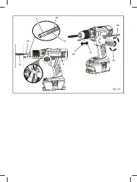
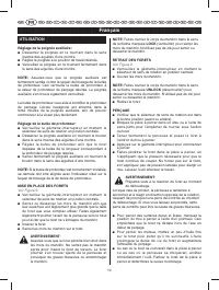
ADJUSTING THE AUXILIARY HANDLE ASSEMBLY
AND DEPTH STOP ROD
See Figure 10.
An auxiliary handle is packed with the drill for ease of
operation and to help prevent loss of control. The handle can
be mounted on the opposite side for left or right hand use.
To adjust the auxiliary handle assembly:
■
Loosen the handle assembly by turning the handle
counterclockwise.
■
Inser t the auxiliary handle assembly in the desired
operating position.
■
Securely tighten by tur ning the auxiliar y handle
clockwise.
NOTE:
Be sure the auxiliary handle is securely tightened
against the depth stop rod clamp. This secures the depth
stop rod at the desired depth of cut. It also secures the
auxiliary handle.
The depth stop rod helps control the depth of drilled
holes. For convenience and ease of starting threads, the
hex nut has been trapped inside the molded slot in the
auxiliary handle.
To adjust the depth stop rod:
■
Lock the switch trigger by placing the rotation selector
in the center position.
■
Loosen the auxiliary handle assembly by turning the
knob counterclockwise.
■
Adjust the depth stop rod so that the drill bit extends
beyond the end of the rod to the required drilling
depth.
■
Tighten the auxiliary handle assembly by turning the
knob clockwise.
NOTE:
When properly installed, the teeth on the depth
stop rod should be aligned with the teeth indicator on the
depth stop rod clamp.
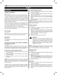
INSTALLING BITS
See Figure 9.
■
Lock the switch trigger by placing the rotation selector
in the center position.
■
Open or close the chuck jaws to a point where the
opening is slightly larger than the bit size you intend
to use. Also, raise the front of the drill slightly to keep
the bit from falling out of the chuck jaws.
■
Insert the drill bit.
■
Tighten the chuck jaws on the drill bit.
WARNING
:
Make sure to insert the drill bit straight into the
chuck jaws. Do not inser t the drill bit into the
chuck jaws at an angle then tighten. This could
cause the drill bit to be thrown from the drill,
resulting in possible serious personal injury or
damage to the chuck.
NOTE:
Rotate the chuck body in the direction of the
arrow marked
LOCK
to tighten the chuck jaws. Do not
use a wrench to tighten or loosen the chuck jaws.
REMOVING BITS
See Figure 9.
■
Lock the switch trigger by placing the rotation selector
in the center position.
■
Open the chuck jaws.
NOTE:
Rotate the chuck body in the direction of the
arrow marked
UNLOCK
to loosen the chuck jaws. Do
not use a wrench to tighten or loosen the chuck jaws.
■
Remove the drill bit.
DRILLING
■
Check the rotation selector for the correct setting
(forward or reverse).
■
Secure the material to be drilled in a vise or with
clamps to keep it from turning as the drill bit rotates.
■
Hold the drill firmly and place the bit at the point to be
drilled.
Содержание
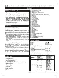
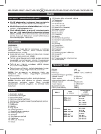
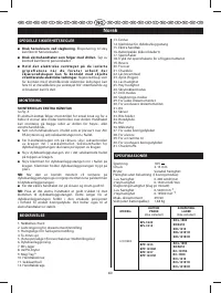
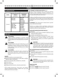
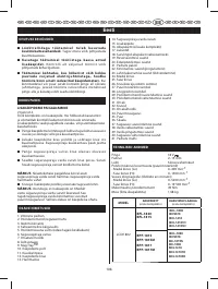
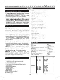
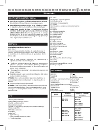
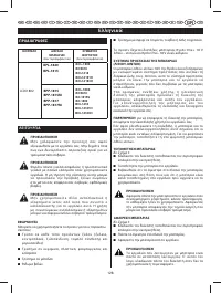
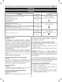
- 71 ТЕХНИЧЕСКИЕ ХАРАКТЕРИС ТИКИ; ОБЛАСТИ ПРИМЕНЕНИЯ; Это изделие можно использовать для следующих целей.; УСТАНОВКА АККУМУЛЯТОРНОЙ БАТАРЕИ; Установите аккумуляторную батарею на инструмент.; СНЯТИЕ АККУМУЛЯТОРНОЙ БАТАРЕИ; Снимите аккумуляторную батарею с инструмента.; МОДЕЛЬ
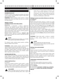
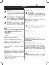
- 72 ЭКСПЛУАТАЦИЯ
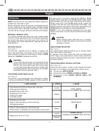
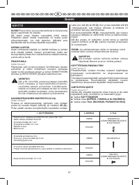
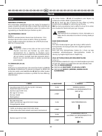
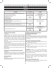
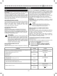
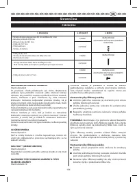
- 73 èÖêÖäãûóÄíÖãú êÖÜàåéÇ; Выберите необходимую; Выберите нужную; РЕГУЛИРОВКА КРУТЯЩЕГО МОМЕНТА; ОТДЕЛЕНИЕ ДЛЯ НАСАДОК; РЕЕЧНОГО ОГРАНИЧИТЕЛЯ ГЛУБИНЫ
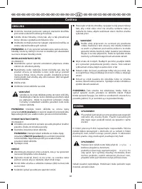
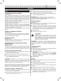
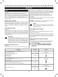
- 74 УСТАНОВКА СВЕРЛА
- 75 ПРЕДУПРЕЖДЕНИЕ; ЗАЩИТА ОКРУ ЖАЮЩЕЙ СРЕДЫ


