Пилы дисковые Einhell TC-TS 254 - инструкция пользователя по применению, эксплуатации и установке на русском языке. Мы надеемся, она поможет вам решить возникшие у вас вопросы при эксплуатации техники.
Если остались вопросы, задайте их в комментариях после инструкции.
"Загружаем инструкцию", означает, что нужно подождать пока файл загрузится и можно будет его читать онлайн. Некоторые инструкции очень большие и время их появления зависит от вашей скорости интернета.


GB
- 28 -
surface and the surface on which it is stood to
prevent any damage to the table surface.
•
Important! Only fasten all the screw connec-
tions between the base frame and machine
loosely at first. Wait until you have returned
the bench-type circular saw to its working po-
sition before tightening the screw connections
securely. This is so that you can be sure the
base frame is aligned level with the surface
on which it is stood.
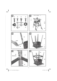
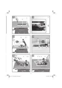
•
Use the hexagon screws (43) and washers
(44) to fasten the four legs (29) loosely to the
saw.
•
Then use the lock bolt (45), washer (46),
spring washer (47) and nut (48) to screw the
cross-struts loosely to the legs. Make sure
that the tongue-and-groove connection bet-
ween the cross-strut (30) and leg (29) enga-
ges properly.
•
Plug the rubber feet (13) onto the legs (29).
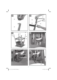
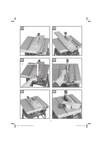
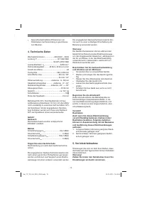
6.2 Standing the bench-type circular saw up-
right (2, 7-9)
•
Turn the machine over so that it stands on its
legs.
•
The bench-type circular saw must be stood
on a flat surface.
•
Then tighten all loose screw connections. Use
both the wrenches (38) and (39) to do this.
•
Screw the additional legs (37 to the rear legs
(29) so that they point towards the rear of the
machine. Us the screws (49), washers (46)
and nuts (48) to fasten them.
•
Warning! Don not fit the additional legs (37)
too far away from the surface on which the
machine stands; they are intended to provide
protection against tipping over.
•
Remove the screw (35) from the shaft (25).
•
Slide the hand wheel (8) and then the crank
(10) onto the shaft (25) as shown in Fig. 9.
•
Important! The shaft (25) and the crank (10)
engage with a positive fit, i.e. the flat surface
on the shaft (25) and the flat surface in the
hub of the crank (10) must lie on top of each
other to enable the crank (10) to be slid on.
•
Secure the hand wheel (8) and crank (10)
with the screw (35).
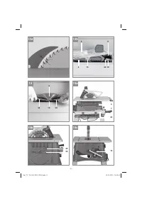
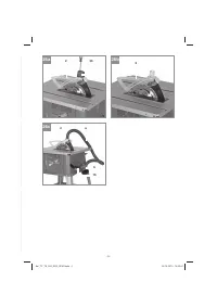
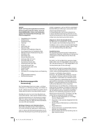
6.3 Changing the table insert (Figure 12)
•
To prevent increased likelihood of injury, the
table insert should be changed whenever it is
worn or damaged.
•
Remove the countersunk head screws (17).
•
Remove the worn table insert (6) by pulling it
out through the opening at the back past the
splitter (5) and the saw blade (4).
•
Fit the replacement table insert by following
the above in reverse.
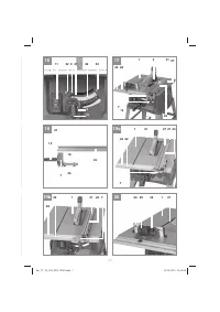
6.4 Fitting / removing the splitter together
with the saw blade guard (Fig. 10 - 13)
•
Remove the table insert (6) by undoing the
countersunk head screws (17) (see 6.3).
•
Using the crank (10) set the saw blade (4) to
the maximum cutting depth.
•
Slacken the fastening screw (19) until the
gap between the fastening plate (40) and the
support surface opposite is approx. 5 mm.
Caution! Do not completely undo the faste-
ning plate (40).
•
Insert the splitter (5) together with the saw
blade guard in the gap, push it right down as
far as it goes and then secure it with the fas-
tening screw (19). Make sure that the splitter
has been fitted straight and not wobbly.
•
The splitter (5) must be positioned in the cen-
ter along an imaginary line extending behind
the saw blade (4), so that it is not possible for
the material to get jammed.
•
The gap between the blade (4) and the split-
ter (5) should be 3 mm to 8 mm. (Fig. 13)
•
Push the table insert (6) through the opening
at the back over the saw blade (4) and the
splitter (5) and insert it in the saw table (1).
•
Use countersunk head screws (17) to fasten
the table insert (6).
•
To dismantle, proceed in reverse order.
6.5 Fitting/changing the saw blade (Fig. 14)
•
Before changing the saw blade: Pull out the
power plug!
•
Wear work gloves to prevent injury when
changing the saw blade.
•
Using the crank (10) set the saw blade (4) to
the maximum cutting depth.
•
Remove the table insert (6) by undoing the
countersunk head screw (17) (see 6.3).
•
Remove the splitter (5) together with the saw
blade guard (2) (see 6.4).
•
Undo the screw (15) with a wrench (38) on
the screw (15) itself and a second wrench
(39) on the motor shaft to apply counter-
pressure.
•
Caution! Turn the screw (15) in the direction
of rotation of the saw blade.
•
Take off the outer flange and pull the old saw
blade (4) off the inner flange.
•
Clean the blade flange thoroughly before fit-
ting the new blade.
•
Fit and fasten the new saw blade (4) in rever-
Anl_TC_TS_254_ECO_SPK9.indb 28
Anl_TC_TS_254_ECO_SPK9.indb 28
25.10.2019 10:22:49
25.10.2019 10:22:49
Характеристики

Остались вопросы?Не нашли свой ответ в руководстве или возникли другие проблемы? Задайте свой вопрос в форме ниже с подробным описанием вашей ситуации, чтобы другие люди и специалисты смогли дать на него ответ. Если вы знаете как решить проблему другого человека, пожалуйста, подскажите ему :)


