
Перфораторы Makita DHR282ZJ - инструкция пользователя по применению, эксплуатации и установке на русском языке. Мы надеемся, она поможет вам решить возникшие у вас вопросы при эксплуатации техники.
Если остались вопросы, задайте их в комментариях после инструкции.
"Загружаем инструкцию", означает, что нужно подождать пока файл загрузится и можно будет его читать онлайн. Некоторые инструкции очень большие и время их появления зависит от вашей скорости интернета.


16 ENGLISH
NOTE:
This function does not work if the acceleration
does not reach the predetermined one when the tool
is swung.
NOTE:
If the bit is swung at the predetermined
acceleration during chipping, scaling, or demolishing,
the motor is forcibly stopped. In this case, release
the switch trigger, and then pull the switch trigger to
restart the tool.
ASSEMBLY
CAUTION:
Always be sure that the tool is
switched off and the battery cartridge is removed
before carrying out any work on the tool.
Side grip (auxiliary handle)
CAUTION:
Always use the side grip to ensure
safe operation.
CAUTION:
After installing or adjusting the
side grip, make sure that the side grip is firmly
secured.
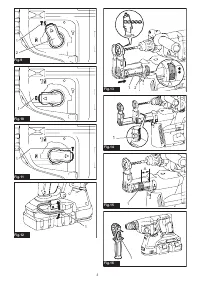
To install the side grip, follow the steps below.
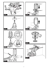
1.
Loosen the thumb screw on the side grip.
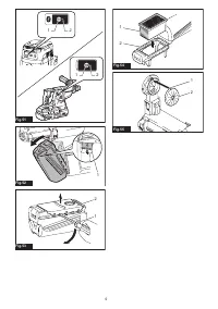
►
Fig.16:
1.
Thumb screw
2.
Attach the side grip while pressing the thumb
screw so that the grooves on the grip fit in the protru
-
sions on the tool barrel.
►
Fig.17:
1.
Thumb screw
3.
Tighten the thumb screw to secure the grip. The
grip can be fixed at desired angle.
Grease
Coat the shank end of the drill bit beforehand with a
small amount of grease (about 0.5 - 1 g).
This chuck lubrication assures smooth action and lon-
ger service life.
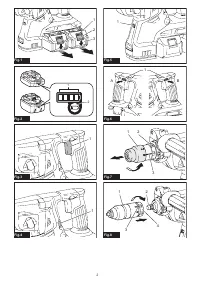
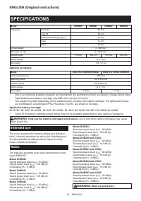
Installing or removing drill bit
Clean the shank end of the drill bit and apply grease
before installing the drill bit.
►
Fig.18:
1.
Shank end
2.
Grease
Insert the drill bit into the tool. Turn the drill bit and push
it in until it engages.
After installing the drill bit, always make sure that the
drill bit is securely held in place by trying to pull it out.
►
Fig.19:
1.
Drill bit
To remove the drill bit, pull the chuck cover down all the
way and pull the drill bit out.
►
Fig.20:
1.
Drill bit
2.
Chuck cover
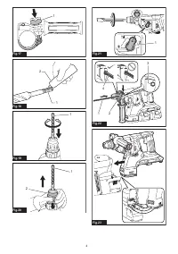
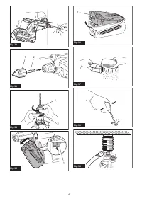
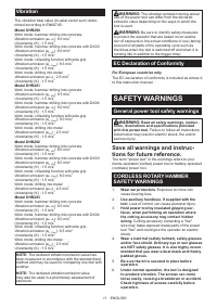
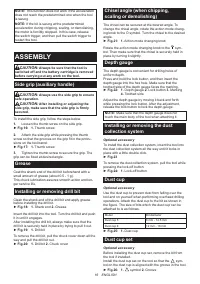
Chisel angle (when chipping,
scaling or demolishing)
The chisel can be secured at the desired angle. To
change the chisel angle, rotate the action mode chang-
ing knob to the O symbol. Turn the chisel to the desired
angle.
►
Fig.21:
1.
Action mode changing knob
Rotate the action mode changing knob to the sym-
bol. Then make sure that the chisel is securely held in
place by turning it slightly.
Depth gauge
The depth gauge is convenient for drilling holes of
uniform depth.
Press and hold the lock button, and then insert the
depth gauge into the hex hole. Make sure that the
toothed side of the depth gauge faces the marking.
►
Fig.22:
1.
Depth gauge
2.
Lock button
3.
Marking
4.
Toothed side
Adjust the depth gauge by moving it back and forth
while pressing the lock button. After the adjustment,
release the lock button to lock the depth gauge.
NOTE:
Make sure that the depth gauge does not
touch the main body of the tool when attaching it.
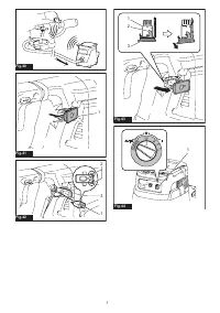
Installing or removing the dust
collection system
Optional accessory
To install the dust collection system, insert the tool into
the dust collection system all the way until it locks in
place with a little double click.
►
Fig.23
To remove the dust collection system, pull the tool while
pressing the lock-off button.
►
Fig.24:
1.
Lock-off button
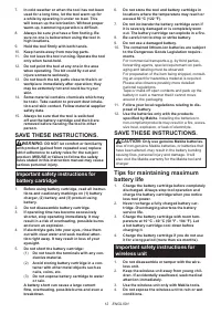
Dust cup
Optional accessory
Use the dust cup to prevent dust from falling over the
tool and on yourself when performing overhead drilling
operations. Attach the dust cup to the bit as shown in
the figure. The size of bits which the dust cup can be
attached to is as follows.
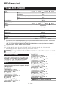
Model
Bit diameter
Dust cup 5
6 mm - 14.5 mm
Dust cup 9
12 mm - 16 mm
►
Fig.25:
1.
Dust cup
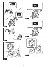
Dust cup set
Optional accessory
Before installing the dust cup set, remove the bit from
the tool if installed.
Install the dust cup set on the tool so that the
sym-
bol on the dust cup is aligned with the groove in the tool.
►
Fig.26:
1.
symbol
2.
Groove
Содержание
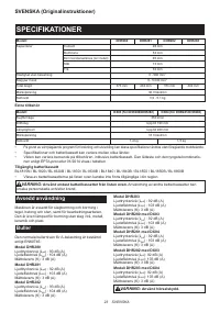
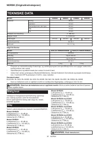
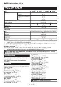
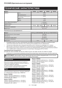
- 101 ТЕХНИЧЕСКИЕ ХАРАКТЕРИСТИКИ; Назначение
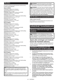
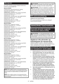
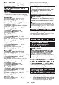
- 102 МЕРЫ БЕЗОПАСНОСТИ; Сохраните брошюру с инструк
- 103 Важные правила техники; СОХРАНИТЕ ДАННЫЕ
- 104 Советы по обеспечению мак
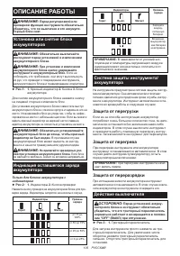
- 105 ОПИСАНИЕ РАБОТЫ; Защита от перегрузки
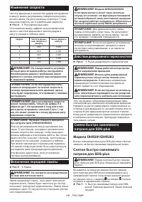
- 106 Изменение скорости; Включение передней лампы
- 107 Установка быстро cменяемого
- 108 СБОРКА
- 109 Колпак для пыли в сборе; ЭКСПЛУАТАЦИЯ; Сверление с ударным действием
- 110 Сверление дерева или металла; Сверление колонковым; Груша для продувки
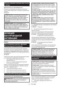
- 111 ФУНКЦИЯ
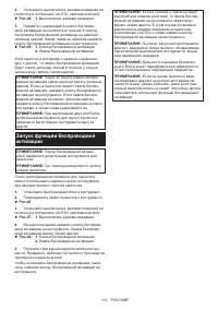
- 112 Запуск функции беспроводной
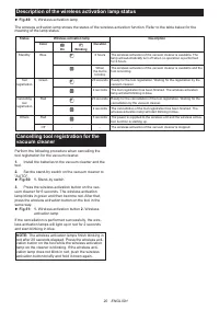
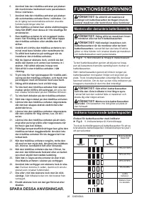
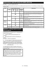
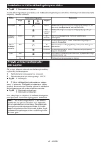
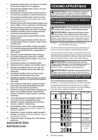
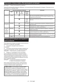
- 113 Описание статуса лампы беспроводной активации
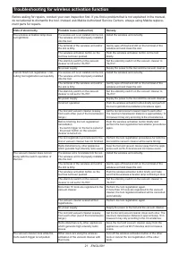
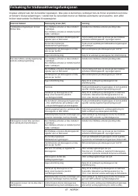
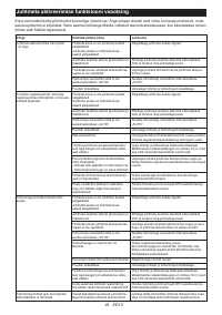
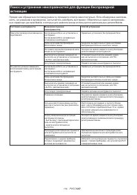
- 114 Поиск и устранение неисправностей для функции беспроводной
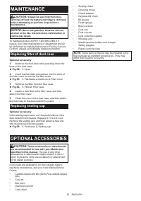
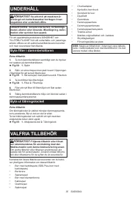
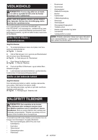
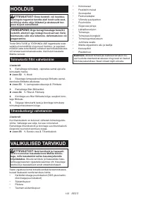
- 115 ОБСЛУЖИВАНИЕ; Замена фильтра корпуса для; Замена уплотнительной крышки; ДОПОЛНИТЕЛЬНЫЕ
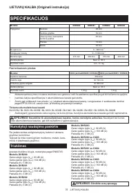
Характеристики

Остались вопросы?Не нашли свой ответ в руководстве или возникли другие проблемы? Задайте свой вопрос в форме ниже с подробным описанием вашей ситуации, чтобы другие люди и специалисты смогли дать на него ответ. Если вы знаете как решить проблему другого человека, пожалуйста, подскажите ему :)


