
Мультиметры BENNING MM P3 044084 - инструкция пользователя по применению, эксплуатации и установке на русском языке. Мы надеемся, она поможет вам решить возникшие у вас вопросы при эксплуатации техники.
Если остались вопросы, задайте их в комментариях после инструкции.
"Загружаем инструкцию", означает, что нужно подождать пока файл загрузится и можно будет его читать онлайн. Некоторые инструкции очень большие и время их появления зависит от вашей скорости интернета.


02/ 2018
BENNING MM P3
20
sion, if they are undamaged.
- Please protect the connected black and red safety measuring leads against con-
tamination and damages!
- Check insulation of the safety measuring leads. If the insulation is damaged,
multimeter must be replaced immediately.
- Check the safety measuring leads for continuity. If the conductor in the safety
measuring lead is interrupted, replace the multimeter immediately.
- Before selecting another function by means of the rotary switch
7
, disconnect
the safety measuring leads from the measuring point.
- Strong sources of interference in the vicinity of the BENNING MM P3 might involve
unstable readings and measuring errors.
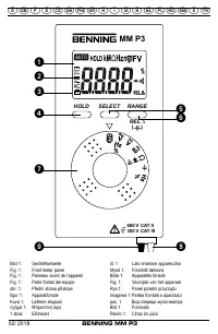
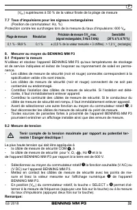
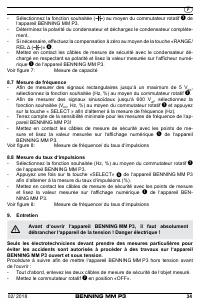
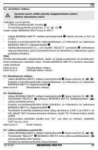
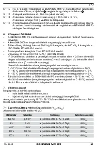
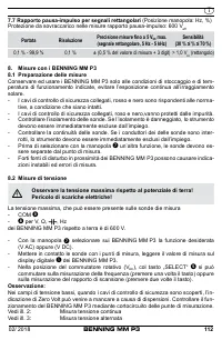
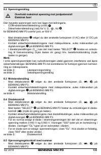
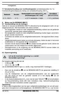
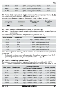
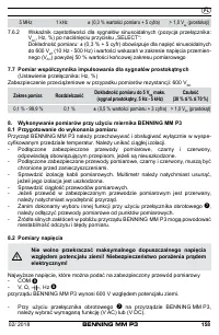
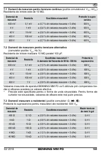
8.2 Voltage measurement
Do not exceed the maximum permitted voltage with respect to earth
potential! Electrical danger!
The highest voltage which may be applied to the
- COM safety measuring lead (black)
J
- safety measuring lead (red) for
V, Ω,
, Hz
9
of the BENNING MM P3 against ground is 600 V.
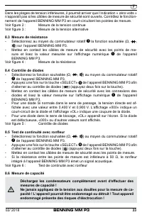
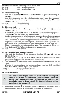
- Select the desired function (V AC) or (V DC) by means of the rotary switch
7
of
the BENNING MM P3.
-
Bring the safety measuring leads into contact with the measuring
points and read the measured value on the digital display
of the
BENNING MM P3.
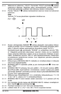
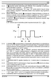
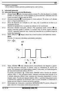
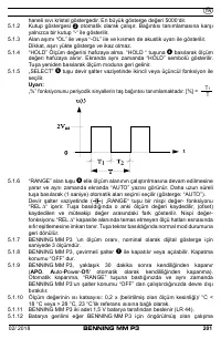
- Use the „SELECT“ key
5
in switch setting (V
AC
) to switch over to frequency
measurement (press the key once) or to pulse-duty factor measurement (press
the key twice).
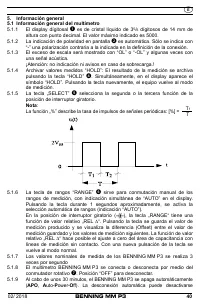
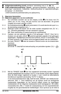
Note:
In lower voltage ranges, the „zero volt“ indication might fail to appear due to interfer-
ence, if the safety measuring leads are open. Check the BENNING MM P3 for correct
functioning by short-circuiting the measuring probes.
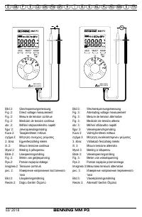
See figure 2:
DC voltage measurement
See figure 3:
AC voltage measurement
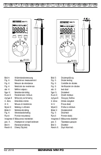
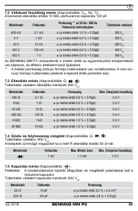
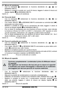
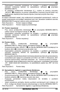
8.3 Resistance measurement
- Select the desired function (Ω,
, ) by means of the rotary switch
7
of the
BENNING MM P3
-
Bring the safety measuring leads into contact with the measuring
points and read the measured value on the digital display
of the
BENNING MM P3.
See figure 4:
Resistance measurement
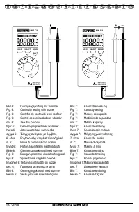
8.4 Diode test
- Select the desired function (Ω,
, ) by means of the rotary switch
7
of the
BENNING MM P3.


