
Мультиметры BENNING MM 1-3 044083 - инструкция пользователя по применению, эксплуатации и установке на русском языке. Мы надеемся, она поможет вам решить возникшие у вас вопросы при эксплуатации техники.
Если остались вопросы, задайте их в комментариях после инструкции.
"Загружаем инструкцию", означает, что нужно подождать пока файл загрузится и можно будет его читать онлайн. Некоторые инструкции очень большие и время их появления зависит от вашей скорости интернета.


19
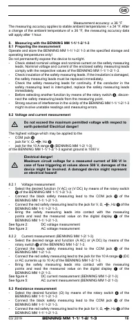
-
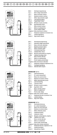
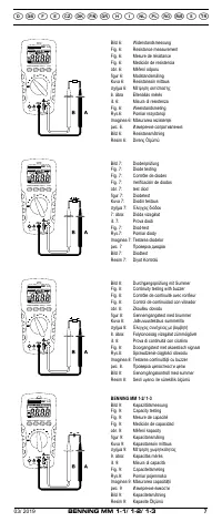
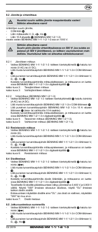
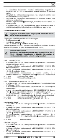
Bring the safety measuring leads into contact with the measuring
points and read the measured value on the digital display
of the
BENNING MM 1-1/ 1-2/ 1-3.
See figure 6:
Resistance measurement
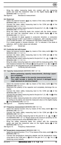
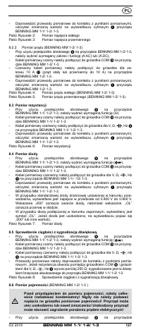
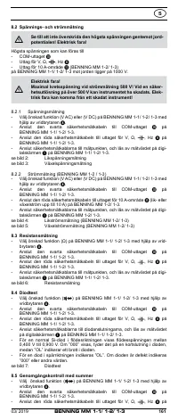
8.4 Diode test
- Select the desired function (
) by means of the rotary switch
8
of the
BENNING MM 1-1/ 1-2/ 1-3.
- Connect the black safety measuring lead to the COM jack
J
of the
BENNING MM 1-1/ 1-2/ 1-3.
- Connect the red safety measuring lead to the jack for V,
,
, Hz
9
of the
BENNING MM 1-1/ 1-2/ 1-3.
- Bring the safety measuring leads into contact with the diode connec-
tions and read the measured value on the digital display
of the
BENNING MM 1-1/ 1-2/ 1-3.
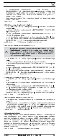
- For a standard Si diode applied in conduction direction, a conduction
voltage between 0.400 V and 0.900 V is displayed. „000“ indicates a short-
circuit inside the diode, „OL“ indicates an interruption inside the diode.
- For a diode applied in reverse direction, „OL“ is indicated. If the diode is
defective, „000“ or other values are indicated.
See figure 7:
Diode test
8.5 Continuity test with buzzer
- Select the desired function (
) by means of the rotary switch
8
of the
BENNING MM 1-1/ 1-2/ 1-3.
- Connect the black safety measuring lead to the COM jack
J
of the
BENNING MM 1-1/ 1-2/ 1-3.
- Connect the red safety measuring lead to the jack for V,
,
, Hz
9
of the
BENNING MM 1-1/ 1-2/ 1-3.
- Bring the safety measuring leads into contact with the measuring points. If the
lead resistance between the COM jack
J
and the jack for V,
,
, Hz
9
falls
below 250
, the integrated buzzer of the BENNING MM 1-1/ 1-2/ 1-3 sounds.
See figure 8:
Continuity test with buzzer
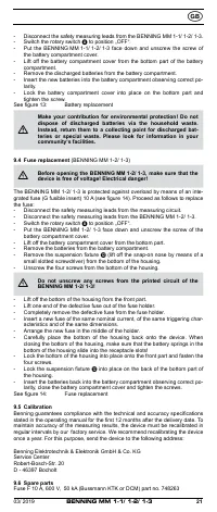
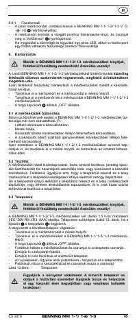
8.6 Capacity measurement
(BENNING MM 1-2/ 1-3)
Before performing capacity measurements, discharge capaci
‑
tors completely!
Never apply voltage to the capacity measurement jacks!
This might damage or destroy the device! A damaged device
might represent an electrical hazard!
- Select the desired function (
) by means of the rotary switch
8
of the
BENNING MM 1-2/ 1-3.
- Determine the polarity of the capacitor and completely discharge the ca-
pacitor.
- Connect the black safety measuring lead to the COM jack
J
of the
BENNING MM 1-2/ 1-3.
- Connect the red safety measuring lead to the jack for V,
,
, Hz
9
of the
BENNING MM 1-2/ 1-3.
- Bring the safety measuring leads into contact with the discharged capacitor
according to ist polarity and read the measured value on the digital display
of the BENNING MM 1-2/ 1-3.
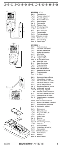
See figure 9:
Capacity measurement
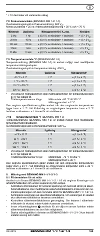
8.7 Frequency measurement
(BENNING MM 1-2/ 1-3)
- Select the desired function (Hz) by means of the rotary switch
8
of the
BENNING MM 1-2/ 1-3.
- Connect the black safety measuring lead to the COM jack
J
of the
BENNING MM 1-2/ 1-3.
- Connect the red safety measuring lead to the jack for V,
,
, Hz
9
of
the BENNING MM 1-2/ 1-3. Please observe the minimum sensitivity for fre-
quency measurements of the BENNING MM 1-2/ 1-3!
-
Bring the safety measuring leads into contact with the measuring
points and read the measured value on the digital display
of the
BENNING MM 1-2/ 1-3.
See figure 10:
Frequency measurement
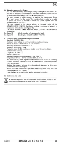
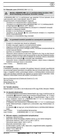
8.8 Temperature measurement
(BENNING MM 1-3)
- Select the desired function (°C or °F) by means of the rotary switch
8
of the
BENNING MM 1-3.
- Connect the temperature measuring adapter and the temperature meas-
uring lead to the COM jack (-)
J
and to the jack for V,
,
, Hz (+)
9
observing correct polarity.
03/ 2019
BENNING MM 1-1/ 1-2/ 1-3


