Материнские платы GIGABYTE GA X58A UD5 rev 1 0 - инструкция пользователя по применению, эксплуатации и установке на русском языке. Мы надеемся, она поможет вам решить возникшие у вас вопросы при эксплуатации техники.
Если остались вопросы, задайте их в комментариях после инструкции.
"Загружаем инструкцию", означает, что нужно подождать пока файл загрузится и можно будет его читать онлайн. Некоторые инструкции очень большие и время их появления зависит от вашей скорости интернета.


- 27 -
Hardware Installation
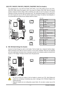
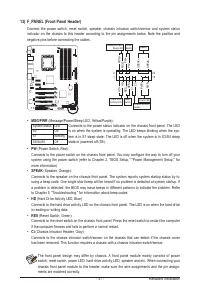
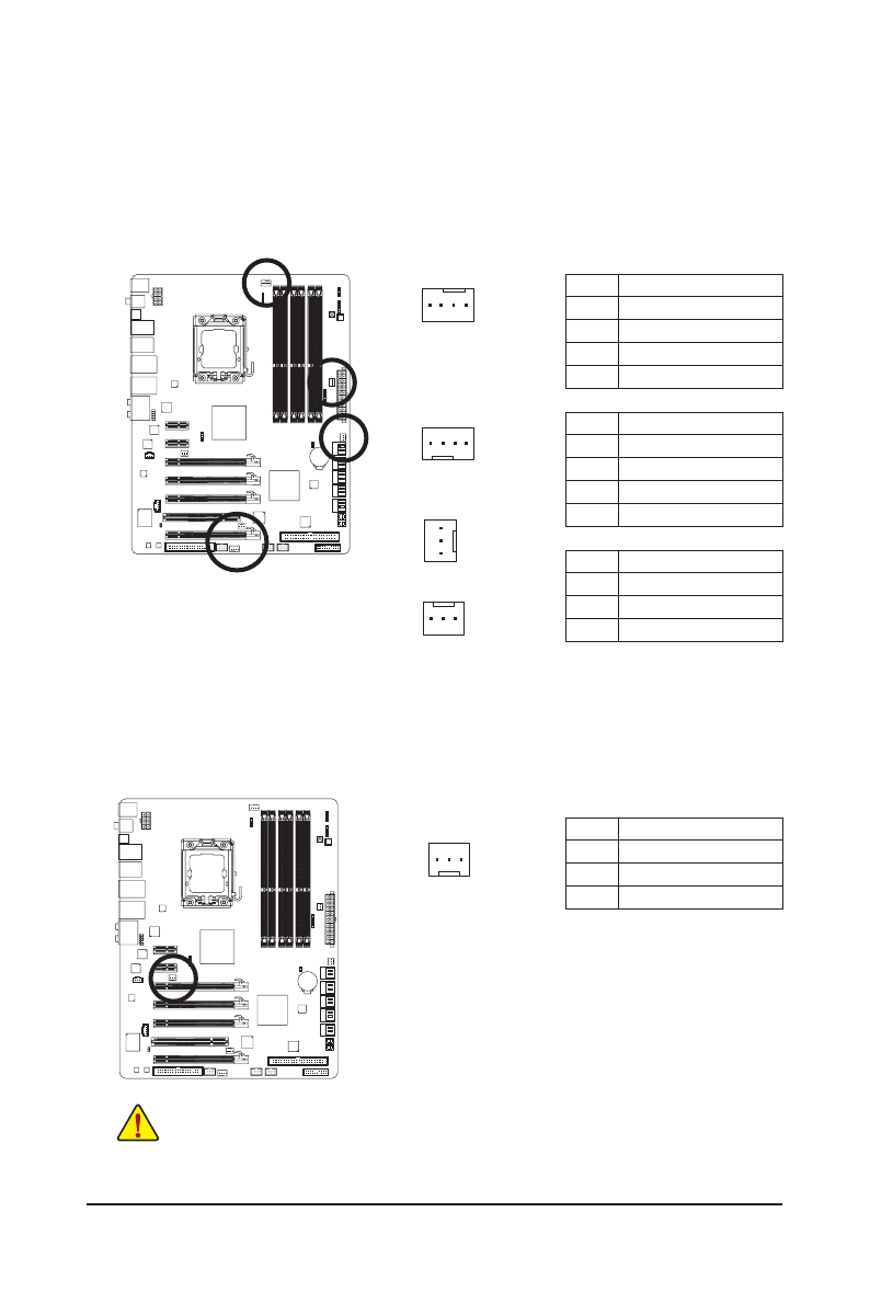
3/4/5) CPU_FAN/SYS_FAN1/SYS_FAN2/SYS_FAN3/PWR_FAN (Fan Headers)
The motherboard has a 4-pin CPU fan header (CPU_FAN), a 4-pin (SYS_FAN2) and two 3-pin (SYS_
FAN1/SYS_FAN3) system fan headers, and a 3-pin power fan header (PWR_FAN). Most fan headers
possess a foolproof insertion design. When connecting a fan cable, be sure to connect it in the correct
orientation (the black connector wire is the ground wire). The motherboard supports CPU fan speed con-
trol, which requires the use of a CPU fan with fan speed control design. For optimum heat dissipation, it
is recommended that a system fan be installed inside the chassis.
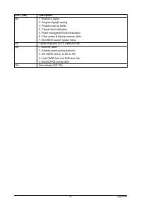
•
Be sure to connect fan cables to the fan headers to prevent your CPU, North Bridge and
system from overheating. Overheating may result in damage to the CPU/North Bridge or the
system may hang.
•
These fan headers are not configuration jumper blocks. Do not place a jumper cap on the
headers.
1
CPU_FAN:
Pin No. Definition
1
GND
2
+12V / Speed Control
3
Sense
4
Speed Control
SYS_FAN2:
Pin No. Definition
1
GND
2
+12V / Speed Control
3
Sense
4
Reserve
SYS_FAN1/SYS_FAN3/PWR_FAN:
Pin No. Definition
1
GND
2
+12V
3
Sense
Pin No. Definition
1
GND
2
+12V
3
NC
6) NB_FAN (North Bridge Fan Header)
Connect the North Bridge fan cable to this header. The fan header has a foolproof insertion design.
When connecting a fan cable, be sure to connect it in the correct orientation. Most fans are designed
with color-coded power connector wires. A red power connector wire indicates a positive connection and
requires a +12V voltage. The black connector wire is the ground wire.
1
CPU_FAN
SYS_FAN2
SYS_FAN1/PWR_FAN
G.QBOFM
G.QBOFM
1
1
SYS_FAN3
1


