Материнские платы GIGABYTE GA P55 USB3 rev 1 0 - инструкция пользователя по применению, эксплуатации и установке на русском языке. Мы надеемся, она поможет вам решить возникшие у вас вопросы при эксплуатации техники.
Если остались вопросы, задайте их в комментариях после инструкции.
"Загружаем инструкцию", означает, что нужно подождать пока файл загрузится и можно будет его читать онлайн. Некоторые инструкции очень большие и время их появления зависит от вашей скорости интернета.


- 24 -
Hardware Installation
1-10 Onboard LEDs and Buttons
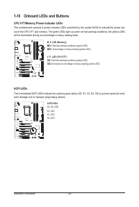
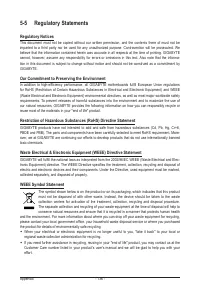
ACPI LEDs
The 4 embedded ACPI LEDs indicate the system power status (S0, S1, S3, S4, S5) to prevent potential hard-
ware damage due to improper plug/unplug actions.
ACPI LEDs:
S4_S5_LED
S3_LED
S1_LED
S0_LED
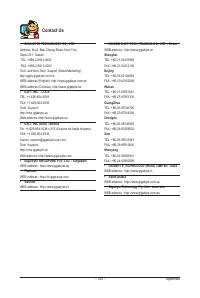
CPU VTT/Memory Phase Indicator LEDs
This motherboard contains 4 phase indicator LEDs controlled by the system BIOS to indicate the phase sta-
tus of the CPU VTT and memory. The green LEDs light up under normal working conditions; the yellow LEDs
will be illuminated during an overvoltage or heavy loading state.
M_P_LED (Memory):
MD1:
Normal working conditions (green LED)
MD2:
Overvoltage or heavy loading (yellow LED)
V_P_LED (CPU VTT):
GD1:
Normal working conditions (green LED)
GD2:
Excessive overvoltage or heavy loading (yellow LED)


