Материнские платы GIGABYTE GA 945G DS3 rev 3 3 - инструкция пользователя по применению, эксплуатации и установке на русском языке. Мы надеемся, она поможет вам решить возникшие у вас вопросы при эксплуатации техники.
Если остались вопросы, задайте их в комментариях после инструкции.
"Загружаем инструкцию", означает, что нужно подождать пока файл загрузится и можно будет его читать онлайн. Некоторые инструкции очень большие и время их появления зависит от вашей скорости интернета.

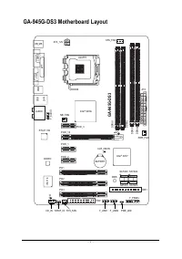


GA-945G-DS3 Motherboard
- 20 -
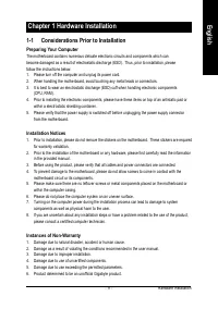
English
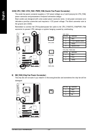
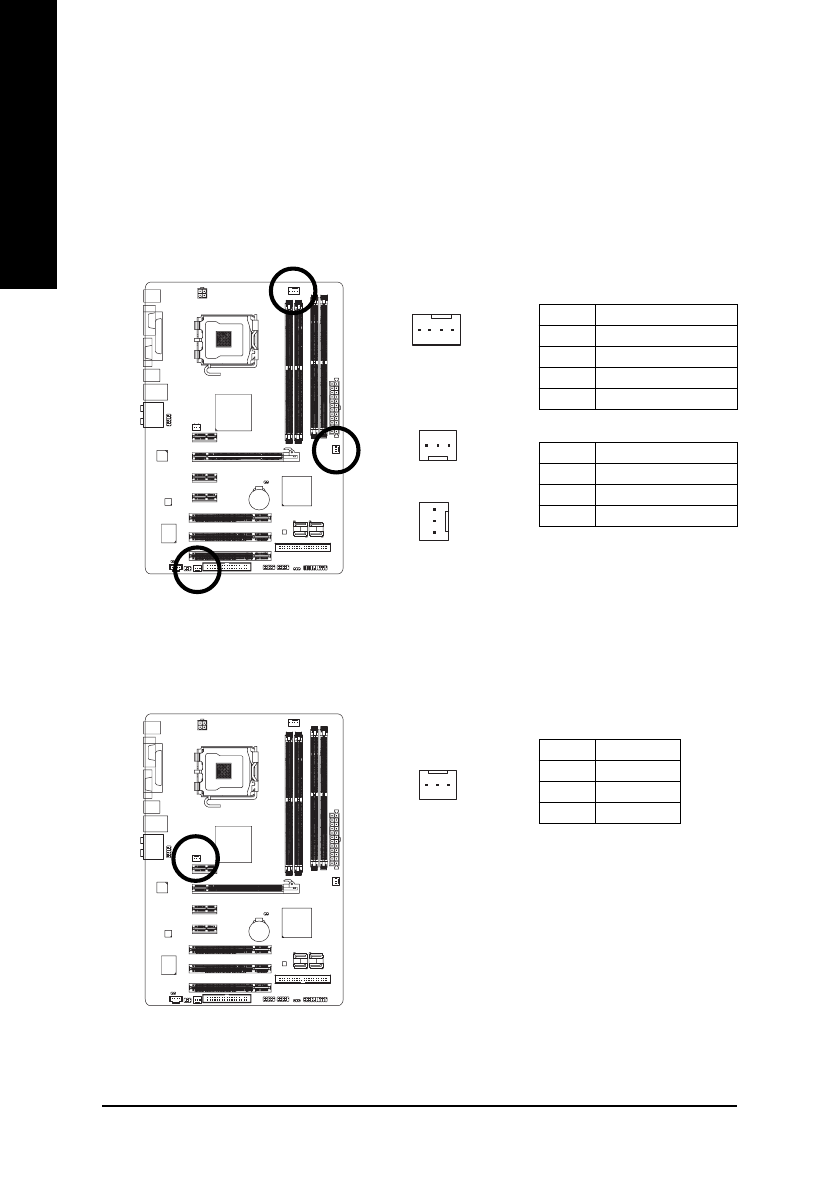
3/4/5) CPU_FAN / SYS_FAN / PWR_FAN (Cooler Fan Power Connector)
The cooler fan power connector supplies a +12V power voltage via a 3-pin/4-pin(only for CPU_FAN)
power connector and possesses a foolproof connection design.
Most coolers are designed with color-coded power connector wires. A red power connector wire
indicates a positive connection and requires a +12V power voltage. The black connector wire is
the ground wire (GND).
Remember to connect the CPU/system/power fan cable to the CPU_FAN/SYS_FAN/PWR_FAN
connector to prevent CPU damage or system hanging caused by overheating.
1
1
Pin No.
Definition
1
GND
2
+12V / Speed Control
3
Sense
4
Speed Control
CPU_FAN
PWR_FAN
CPU_FAN :
Pin No.
Definition
1
GND
2
+12V
3
Sense
SYS_FAN / PWR_FAN :
SYS_FAN
1
6) NB_FAN (Chip Fan Power Connector)
The chip fan will not work if you install it in the wrong direction and sometimes the chip fan will be
damaged.
Pin No.
Definition
1
GND
2
+12V
3
NC
1


