Котел Ferroli DIVAtop MICRO C WF - инструкция пользователя по применению, эксплуатации и установке на русском языке. Мы надеемся, она поможет вам решить возникшие у вас вопросы при эксплуатации техники.
Если остались вопросы, задайте их в комментариях после инструкции.
"Загружаем инструкцию", означает, что нужно подождать пока файл загрузится и можно будет его читать онлайн. Некоторые инструкции очень большие и время их появления зависит от вашей скорости интернета.


DIVAtop MICRO C
33
EN
cod. 3540S270 - 02/2010 (Rev. 00)
•
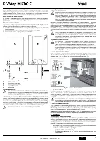
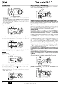
Press the reset button (detail 8 - fig. 1) for 10 seconds.
•
the boiler will return to standby mode
3.
Adjust the minimum and maximum pressures at the burner (refer to relevant sec-
tion), setting the values given in the technical data table for the type of gas used
4.
Apply the sticker contained in the conversion kit, near the dataplate as proof of the
conversion.
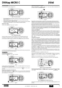
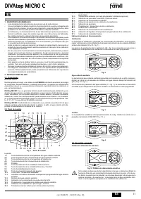
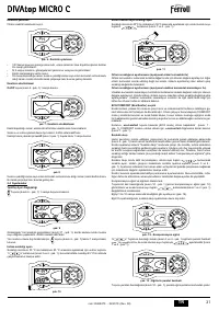
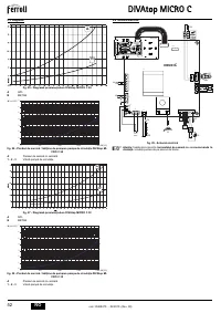
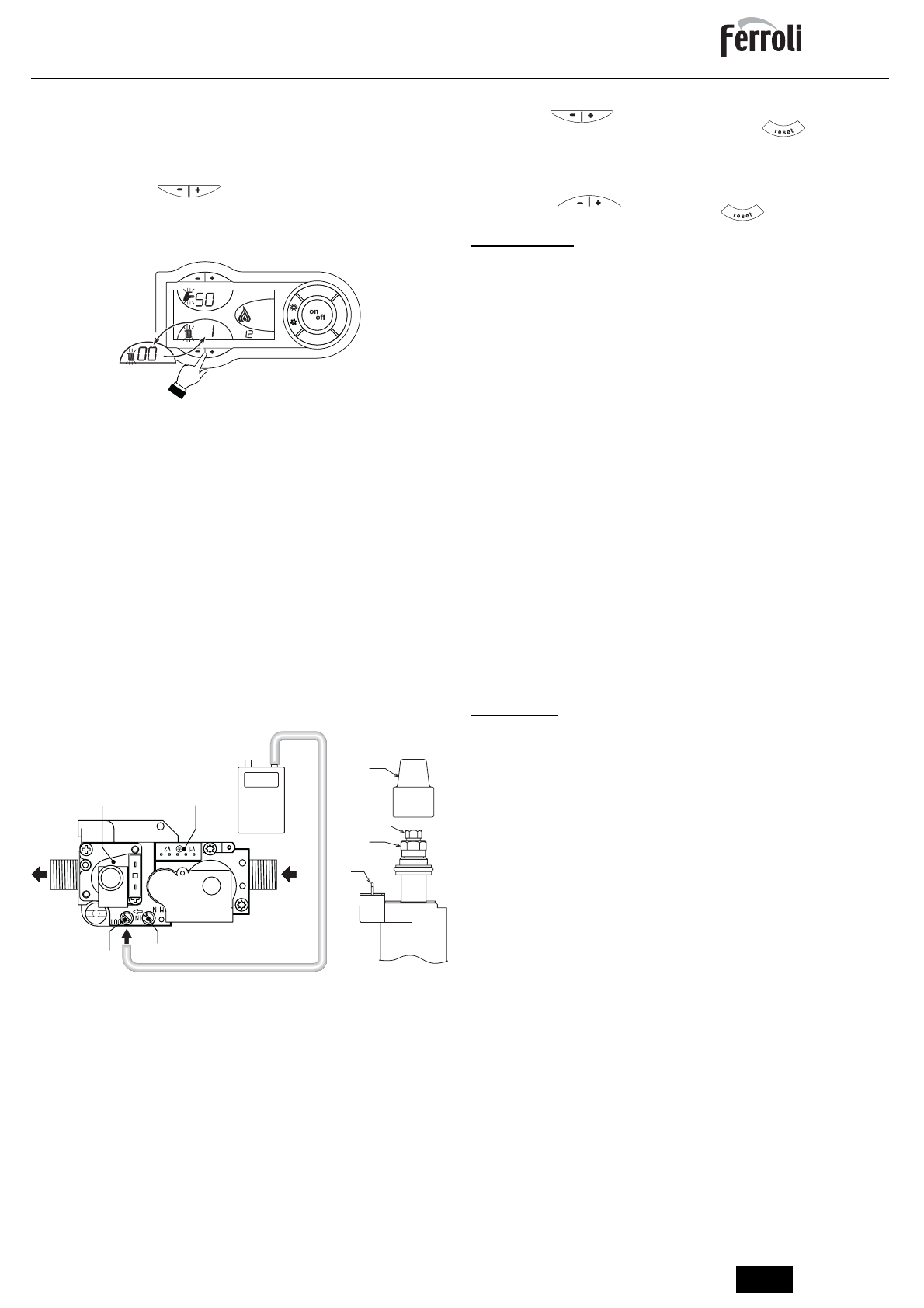
TEST mode activation
Press the heating buttons
(details fig. 13 and 4 -
) at the same time for 5
seconds to activate the
TEST mode. The boiler lights at the maximum heating power
set as described in the following section.
The heating symbol (detail 24 - fig. 1) and DHW symbol (detail 12 - fig. 1) flash on the
display; the heating power and lighting power will be displayed alongside.
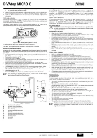
fig. 20 - TEST mode (heating power = 100%)
To deactivate the TEST mode, repeat the activation sequence.
The TEST mode is automatically disabled in any case after 15 minutes.
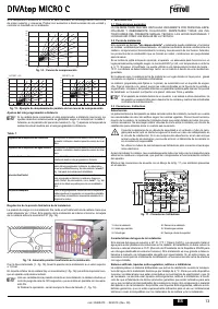
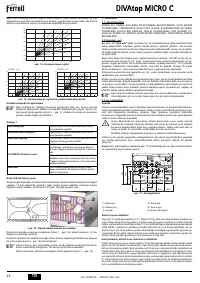
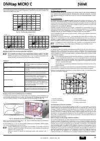
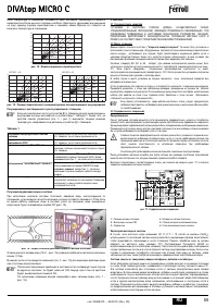
Adjustment of pressure at burner
Since this unit has flame modulation, there are two fixed pressure values: the minimum
and maximum, which must be those given in the technical data table according to the
type of gas.
•
Connect a suitable pressure gauge to the pressure point
"B"
downstream of the
gas valve.
•
Remove the protection cap
"D"
.
•
Operate the boiler in
TEST
fig. 1 mode.
•
Adjust the maximum pressure setting by turning the screw
"G"
clockwise to in-
crease the pressure and anticlockwise to decrease it.
•
Disconnect one of the two fastons
"C"
from modureg
"F"
on the gas valve.
•
Adjust the minimum pressure setting by turning the screw
"E"
clockwise to increase
the pressure and anticlockwise to decrease it.
•
Turn the burner on and off, checking that the minimum pressure remains stable.
•
Reconnect the faston
"C"
detached from the modureg
"F"
on the gas valve
•
Check that the maximum pressure has not changed
•
Refit the protection cap
"D
.
•
To end the
TEST
mode, repeat the activation sequence or wait 15 minutes.
A
After checking or adjusting the pressure, make sure to seal the adjust-
ment screw with paint or a specific seal.
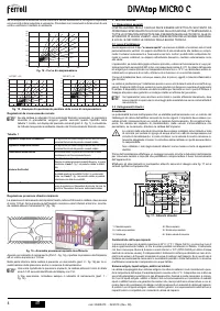
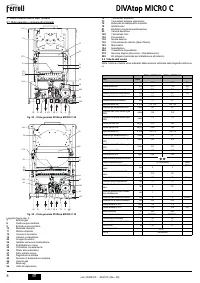
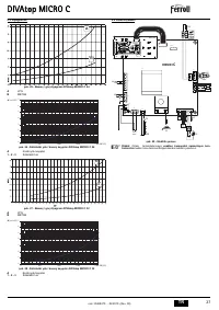
fig. 21 - Gas valve
to
Pressure point upstream
B
Pressure point downstream
C
Modureg electrical connection
D
Protective cap
E
Minimum pressure adjustment
F
Modureg
G
Minimum pressure adjustment
I
Gas valve electrical connection
M
Pressure gauge
R
Gas outlet
S
Gas inlet
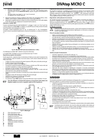
Heating power adjustment
To adjust the heating power, set the boiler on TEST operation (see sec. 4.1). Press the
heating buttons
(part 3 and 4 - fig. 1) to increase or decrease the power
(minimum = 00 - Maximum = 100). Press the RESET button
within 5 seconds
and the maximum power will remain as has just been set. Exit TEST operation (see
sec. 4.1).
Ignition power adjustment
To adjust the ignition power, set the boiler on TEST operation (see sec. 4.1). Press the
tap water buttons
(part 1 and 2 - fig. 1) to increase or decrease the power
(minimum = 00 - Maximum = 60). Press the button
within 5 seconds and the
ignition power will remain as has just been set. Exit TEST operation (see sec. 4.1).
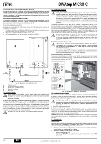
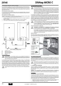
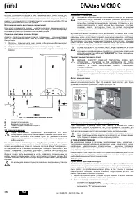
4.2 System start-up
B
Checks to be made at first ignition, and after all maintenance operations that
involved disconnecting from the systems or an intervention on safety devices
or parts of the boiler:
Before lighting the boiler
•
Open any on-off valves between the boiler and the systems.
•
Check the tightness of the gas system, proceeding with caution and using a soap
and water solution to detect any leaks in connections.
•
Check the correct preloading of the expansion tank (ref. sec. 5.2)
•
Fill the water system and make sure that all air contained in the boiler and the sys-
tem has been vented by opening the air vent valve on the boiler and any vent valves
on the system.
•
Make sure there are no water leaks in the system, hot water circuits, connections or
boiler.
•
Check the correct connection of the electric system and the functioning of the earth
system. l
•
Check that the gas pressure value for heating is as required.
•
Make sure there are no flammable liquids or materials in the immediate vicinity of
the boiler
Checks during operation
•
Ignite the appliance as described in sec. 2.3.
•
Check the airtightness of the fuel circuit and water systems.
•
Check the efficiency of the flue and air-fume ducts while the boiler is working.
•
Check that the water is circulating properly between the boiler and the systems.
•
Make sure that the gas valve modulates correctly in both the heating and hot water
production phases.
•
Check the proper ignition of the boiler by performing various tests, turning it on and
off with the room thermostat or remote control.
•
Make sure that the fuel consumption indicated on the meter corresponds to that giv-
en in the technical data table in sec. 5.2.
•
Make sure that with no call for heating the burner correctly ignites on opening a hot
water tap. Check that during heating operation, on opening a hot water tap, the heat-
ing circulator stops and there is a regular production of hot water.
•
Check the parameters are programmed correctly and perform any required custom-
ization (compensation curve, power, temperatures, etc.)
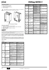
4.3 Maintenance
Periodical check
To ensure proper operation of the unit over time, have qualified personnel carry out a
yearly check, providing for the following:
•
The control and safety devices (gas valve, flowmeter, thermostats, etc.) must func-
tion correctly.
•
The fume exhaust circuit must be perfectly efficient.
(Sealed chamber boiler: fan, pressure switch, etc. - The sealed chamber must be
tight: seals, cable glands, etc.)
(Open chamber boiler: anti-backflow device, fume thermostat, etc.)
•
The air/fume terminal and ducts must be free of obstructions and leaks
•
The burner and exchanger must be clean and free of deposits. For cleaning do not
use chemical products or wire brushes.
•
The electrode must be free of scale and properly positioned.
•
The gas and water systems must be tight.
•
The water pressure in the cold water system must be approx. 1 bar; otherwise bring
it to that value.
•
The circulating pump must not be blocked.
•
The expansion tank must be filled.
•
The gas flowrate and pressure must match that given in the respective tables.
A
The boiler casing, control panel and aesthetic parts can be cleaned with a soft
damp cloth, if necessary soaked in soapy water. Do not use any abrasive de-
tergents and solvents.
eco
co mfort
m
o
d
e
r e s e t
eco
bar
+
M
D
E
G
C
F
F
I
B
A
R
S

