
Газонокосилки VERTO 52G572 - инструкция пользователя по применению, эксплуатации и установке на русском языке. Мы надеемся, она поможет вам решить возникшие у вас вопросы при эксплуатации техники.
Если остались вопросы, задайте их в комментариях после инструкции.
"Загружаем инструкцию", означает, что нужно подождать пока файл загрузится и можно будет его читать онлайн. Некоторые инструкции очень большие и время их появления зависит от вашей скорости интернета.


10
•
Ensure your hands are in correct positions on the handle before
starting up the lawn mower.
•
Hold your hands and feet away from rotating parts. When using rotary
mower keep the grass outlet hole unobstructed.
•
Do not lift or carry the lawn mower with the motor switched on.
•
Remove plug from mains socket:
– whenever you go away from the device,
– before cleaning the grass outlet,
– before checking, cleaning or repairing the device,
– after the device is hit. Ensure the lawn mower is not damaged and
repair the device in authorized service when necessary.
– when the lawn mower starts to vibrate excessively.
MAINTENANCE AND STORING
•
Keep in good condition all nuts, bolts and screws to be sure the lawn
mower operates safely.
•
Protect the lawn mower against humidity.
•
Often check grass container against wear and damage.
•
To keep the operation safe, replace worn out and damaged parts.
•
Be careful when adjusting reel mowers and avoid putting your fingers
between moving blades and fixed parts of the tool.
•
When using a rotary mower ensure you use correct type of blades.
CAUTION! The design is assumed to be safe, protection measures
and additional safety systems are used, nevertheless there is always
a small risk of operational injuries.
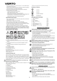
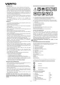
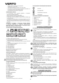
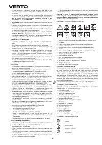
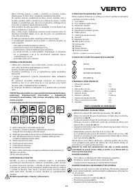
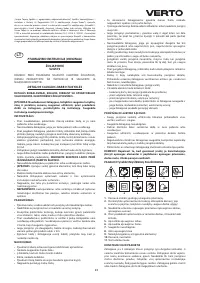
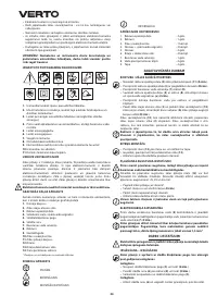
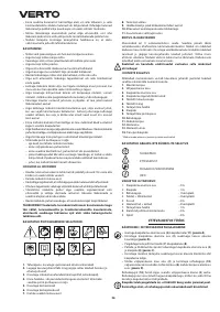
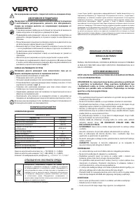
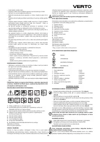
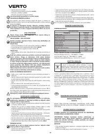
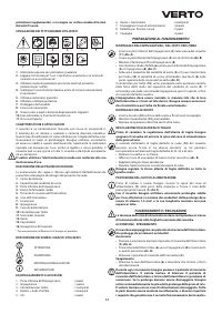
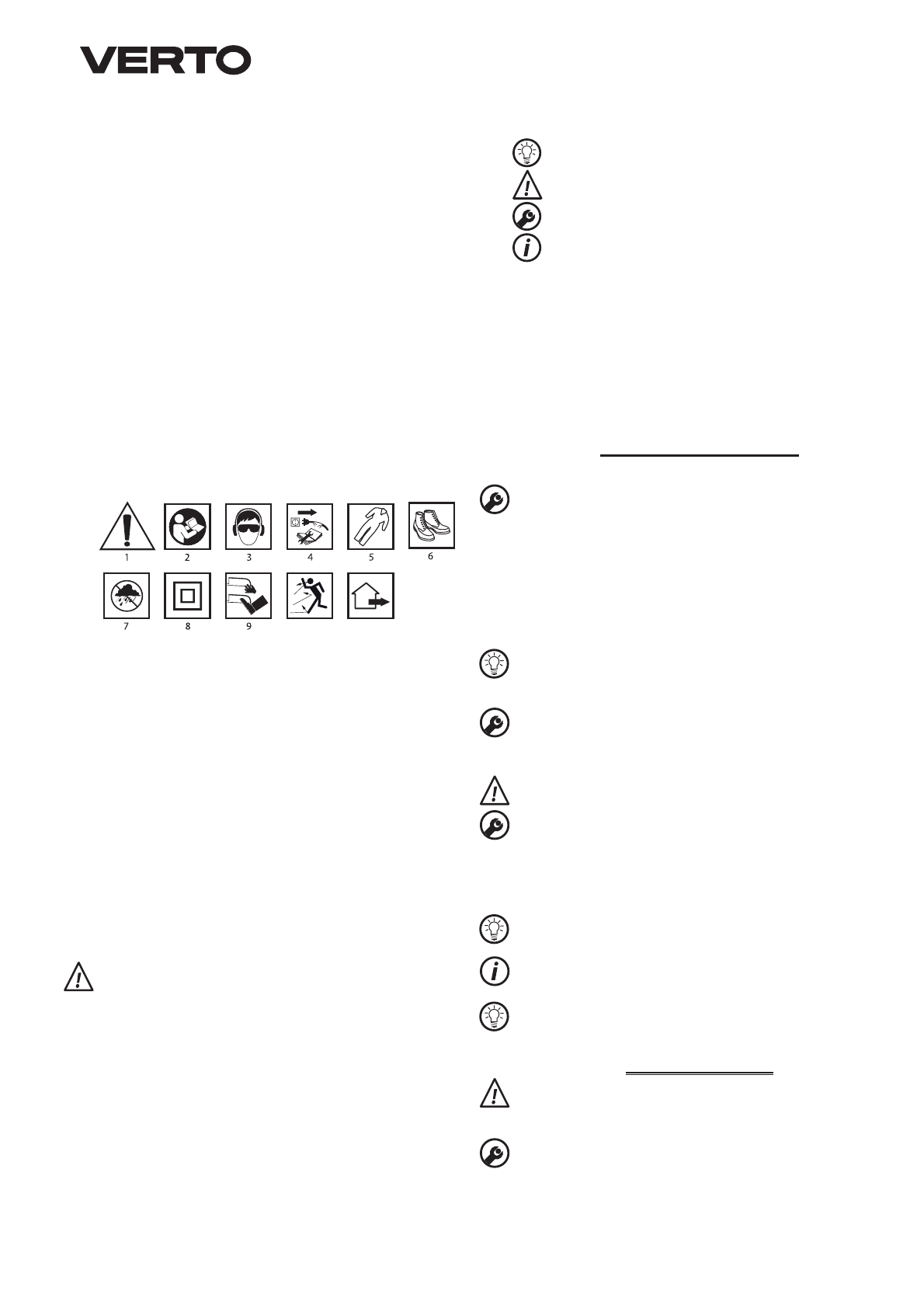
EXPLANATION OF USED SYMBOLS
1
0
11
1.
Caution, use precaution measures
2.
Read instruction manual, observe warnings and safety conditions
therein!
3.
Use personal protection measures (protective goggles, earmuff
protectors)
4.
Disconnect the power cord before starting maintenance or
operation.
5.
Use protective clothes.
6.
Use protective shoes.
7.
Protect against humidity.
8.
Protection class 2
9.
Do not put your hands or legs close to cutting parts.
10.
Watch out for splinters.
11.
For outdoor use.
CONSTRUCTION AND USE
The lawn mower is a device with insulation class II. It is driven by single-
phase AC commutator motor. The lawn mower is designed for mowing
lawn in home garden. Use accessories only designed for this type of
device and follow all instructions contained in the manual. Mow grass
in even strips. Mower can be pushed or pulled. Mower is intended for
amateur use only.
Use the device according to the manufacturer’s instructions only.
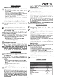
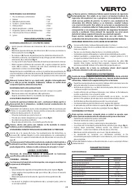
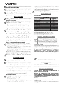
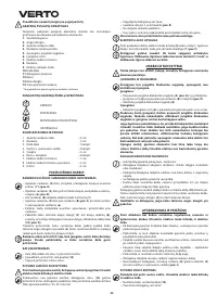
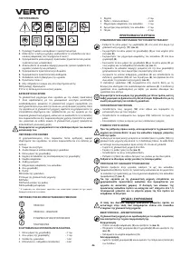
DESCRIPTION OF DRAWING PAGES
Below enumeration refers to the device elements depicted on the
drawing pages of this manual.
1.
Motor casing
2.
Outlet lid
3.
Lower handle part
4.
Butterfly nuts of the joint
5.
Safety button of the switch
6.
Switch lever
7.
Power cord holder
8.
Handle
9.
Power cord
10.
Grass container
11.
Mower body
12.
Ground wheel
13.
Hub cap of ground wheel
14.
Transport handle
* Differences may appear between the product and drawing
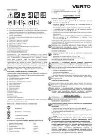
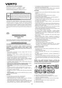
MEANING OF SYMBOLS
CAUTION
WARNING
ASSEMBLY/SETTINGS
INFORMATION
EQUIPMENT AND ACCESSORIES
1. Lower handle part
- 2 pcs
2. Handle
- 1 pce
3
. Grass container
- 1 set
4
. Bolts + butterfly nuts
- 2 sets
5
. Screws
- 2 pcs
6
. Ground wheels + hub caps
-
4
sets
7. Power cord holder
- 1 pce
8
. Clips for power cord holding
- 2 pcs
9
. Cotter
pin
-
4
pcs
PREPARATION FOR OPERATION
INSTALLATION OF HANDLE / GRASS BASKET
•
Put lower handle parts (
3
) in the lawn mower body (
11
) (
fig. A
).
•
Fix lower handle parts (
3
) with the supplied screws (
fig. B
).
•
Attach power cord holder (
7
) to the handle (
8
).
•
Use bolts and butterfly nuts (a) to join lower parts of the handle (
3
)
and the handle (
8
) (
fig. C
).
•
Use supplied clips to fix motor power cord to the handle.
•
Lift outlet lid (
2
) and attach grass container (
10
) to the outlet. Use two
latches (
b
) in the upper part of the mower body (
fig. D
).
Grass container (
10
) is positioned correctly with spring of the outled lid
(
2
). The grass container features comfortable handle to carry and empty
cut grass.
Handle should be installed so the switch lever is on the right side.
Always ensure the grass container is correctly fixed.
INSTALLATION OF GROUND WHEELS
•
Attach ground wheel (
12
) on its axis and secure with cotter pin.
•
Install hub cap (
13
) by pressing it to the ground wheel.
•
Repeat this action for other ground wheels.
ADJUSTING MOWING HEIGHT
Switch off the lawn mower and remove power cord plug from mains
socket before changing mowing height.
Depending on the mowing height, you can install the lawn mower
ground wheels (
12
) in one of three positions. The positions are for
cutting height of 2
5
,
45
and
65
mm.
•
Turn the mower onto its side.
•
Hold the wheel axis and pull (
fig. E
).
•
Change setting to desired position.
•
Repeat procedure for the second pair of wheels.
Set each of the four ground wheels for the same cutting height.
SECURING POWER CORD
Before starting operation, put the power cord plug (
9
) in the extension
cord socket and clamp the extension cord in the power cord holder (
7
)
(
fig. F
).
With the mower use only extension cords designed for outdoor
applications. Cross section of the extension cord cores should be at
least 1.5 mm
2
and maximum length should not exceed 60 m.
OPERATION / SETTINGS
The mains voltage must match the voltage on the rating plate of the
mower.
SWITCHING ON – SWITCHING OFF
The mower is equipped with safety button of the switch, which
protects against accidental starting.
Switching on
•
Press the safety button of the switch (
5
) and hold (
fig. G
).
•
Push the switch lever (
6
) towards the handle (
8
) and hold in this
position (
fig. H
).
•
Release pressure on the safety button of the switch (
5
).

