Электрорубанки Bosch GHO 15-82 - инструкция пользователя по применению, эксплуатации и установке на русском языке. Мы надеемся, она поможет вам решить возникшие у вас вопросы при эксплуатации техники.
Если остались вопросы, задайте их в комментариях после инструкции.
"Загружаем инструкцию", означает, что нужно подождать пока файл загрузится и можно будет его читать онлайн. Некоторые инструкции очень большие и время их появления зависит от вашей скорости интернета.


English |
13
Bosch Power Tools
1 609 92A 11E | (1.12.14)
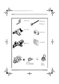
18
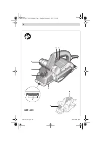
Scale for rebating width
19
Locking nut for adjustment of rebating width
20
Fastening bolt for parallel and beveling guide
21
Angle stop *
22
Locking nut for angle adjustment
23
Fastening bolt for rebating depth stop
24
Rebating depth stop *
* Accessories shown or described are not part of the standard de-
livery scope of the product. A complete overview of accessories
can be found in our accessories program.
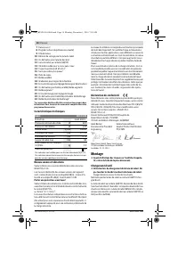
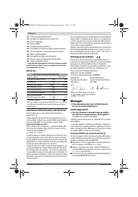
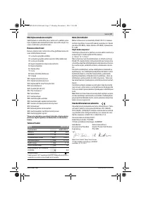
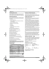
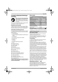
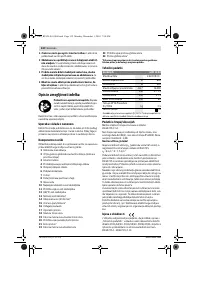
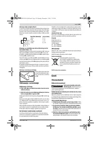
Technical Data
Noise/Vibration Information
Sound emission values determined according to
EN 60745-2-14.
Typically the A-weighted noise levels of the product are:
Sound pressure level 84 dB(A); Sound power level 95 dB(A).
Uncertainty K = 3 dB.
Wear hearing protection!
Vibration total values a
h
(triax vector sum) and uncertainty K
determined according to EN 60745:
a
h
= 8 m/s
2
, K = 1.5 m/s
2
.
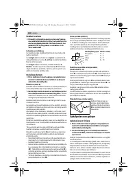
The vibration level given in this information sheet has been
measured in accordance with a standardised test given in
EN 60745 and may be used to compare one tool with anoth-
er. It may be used for a preliminary assessment of exposure.
The declared vibration emission level represents the main ap-
plications of the tool. However if the tool is used for different
applications, with different accessories or insertion tools or is
poorly maintained, the vibration emission may differ. This
may significantly increase the exposure level over the total
working period.
An estimation of the level of exposure to vibration should also
take into account the times when the tool is switched off or
when it is running but not actually doing the job. This may sig-
nificantly reduce the exposure level over the total working
period.
Identify additional safety measures to protect the operator
from the effects of vibration such as: maintain the tool and the
accessories, keep the hands warm, organisation of work pat-
terns.
Declaration of Conformity
We declare under our sole responsibility that the product de-
scribed under “Technical Data” is in conformity with all rele-
vant provisions of the directives 2011/65/EU, 2014/30/EU,
2006/42/EC including their amendments and complies with
the following standards: EN 60745-1, EN 60745-2-14.
Technical file (2006/42/EC) at:
Robert Bosch GmbH, PT/ETM9,
70764 Leinfelden-Echterdingen, GERMANY
Robert Bosch GmbH, Power Tools Division
70764 Leinfelden-Echterdingen, GERMANY
Leinfelden, 01.12.2014
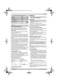
Assembly
Before any work on the machine itself, pull the mains
plug.
Changing the Tool
Be cautious when replacing the planer blades. Do not
grasp the planer blades by the cutting edges.
Possible
danger of injury due to the sharp cutting edges of the plan-
er blades.
Use only original Bosch carbide blades (TC).
The carbide blade (TC) has 2 cutting edges and can be re-
versed. When both cutting edges are dull, the planer blade
12
must be replaced. The carbide blade (TC) may not be resharp-
ened.
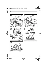
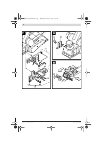
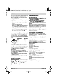
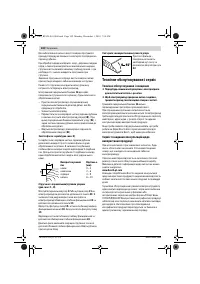
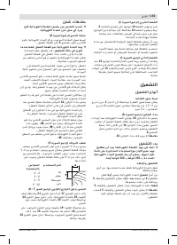
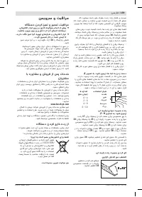
Disassembling the Planer Blade(s) (see figure A)
To reverse or replace the planer blade
12
, rotate the blade
drum
9
until it is parallel to the planer base plate
6
.
Assembling the Planer Blade(s) (see figure B)
The guide groove of the planer blade always ensures continu-
ous height adjustment when replacing or reversing it.
If required, clean the blade seat in the clamping element
10
and the planer blade
12
.
When assembling the planer blade, ensure that it is seated
properly in the blade holder of the clamping element
10
. The
planer blade must be assembled and aligned
centred to the
planer base plate
6
. Afterwards tighten the 2 fastening
screws
11
with the Hex key
13
.
Note:
Before restarting, check if the fastening screws
11
are
tightened well. Rotate the blade drum
9
by hand and ensure
that the planer blade does not graze.
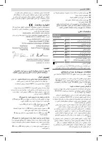
Planer
GHO 15-82
Article number
3 601 E94 0..
Rated power input
W
600
Output power
W
340
No-load speed
min
-1
16 000
Planing depth
mm
0 – 1.5
Rebating depth
mm
0 – 9
Planing width, max.
mm
82
Weight according to
EPTA-Procedure 01/2003
kg
2.5
Protection class
/
II
The values given are valid for a nominal voltage [U] of 230 V. For differ-
ent voltages and models for specific countries, these values can vary.
Henk Becker
Executive Vice President
Engineering
Helmut Heinzelmann
Head of Product Certification
PT/ETM9
Loosen the two fastening screws
11
with the Hex key
13
by
approx. 1 – 2 turns.
If necessary, loosen the clamping element
10
by giving it a
light blow with a suitable tool (e. g. a wooden wedge).
Push the planer blade
12
sidewards out of the blade drum
9
with a piece of wood.
OBJ_BUCH-865-006.book Page 13 Monday, December 1, 2014 7:58 AM
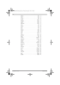
Содержание
- 93 Описание продукта и услуг; Применение по назначению
- 94 Данные по шуму и вибрации; Заявление о соответствии; Сборка; Замена рабочего инструмента; Отсос пыли и стружки
- 95 Работа с инструментом; Режимы работы; Включение электроинструмента; Указания по применению
- 96 Техобслуживание и сервис; Техобслуживание и очистка
- 97 Утилизация
Характеристики

Остались вопросы?Не нашли свой ответ в руководстве или возникли другие проблемы? Задайте свой вопрос в форме ниже с подробным описанием вашей ситуации, чтобы другие люди и специалисты смогли дать на него ответ. Если вы знаете как решить проблему другого человека, пожалуйста, подскажите ему :)


