
Водонагреватели TESY GCR 802724D E31 EC - инструкция пользователя по применению, эксплуатации и установке на русском языке. Мы надеемся, она поможет вам решить возникшие у вас вопросы при эксплуатации техники.
Если остались вопросы, задайте их в комментариях после инструкции.
"Загружаем инструкцию", означает, что нужно подождать пока файл загрузится и можно будет его читать онлайн. Некоторые инструкции очень большие и время их появления зависит от вашей скорости интернета.

7
EN
English
II.
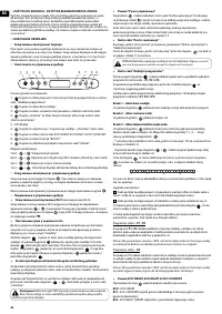
TECHNICAL PARAMETERS
1.
Nominal volume, litres - see the appliance’s rating plate
2.
Nominal voltage - see the appliance’s rating plate
3.
Nominal power consumption - see the appliance’s rating plate
4.
Nominal pressure - see the appliance’s rating plate
This is not the water mains pressure. This is the pressure that is declared for the
appliance and refers to the requirements of the safety standards.
5.
Water heater type – closed type accumulating water heater, with thermal insulation
6.
Daily energy consumption – see Annex I
7.
Rated load profile – see Annex I
8.
Quantity of mixed water at 40°C V40 in litres – see Annex I
9.
Maximum temperature of the thermostat – see Annex I
10.
Default temperature settings – see Annex I
11.
Energy efficiency during water heating – see Annex I
III.
DESCRIPTION AND PRINCIPLE OF OPERATION
The appliance consists of a body, flange at the bottom side (for water heaters
intended for vertical mounting) or at the sides (for water heaters intended for
horizontal mounting), protective plastic panel and a safety-return valve.
1.
The housing consists of two steel tanks (water tanks) and a casing (outer shell)
with heat insulation between them from an environmentally clean high-density
polyurethane foam and a housing (outer shell) with thermal insulation placed in-
between made of ecologically clean high density polyurethane, and two pipes with
thread G½‘’ for cold water supply (marked by a blue ring) and hot water outlet pipe
(marked by a red ring).
The inner tanks, depending on the model, may be two types:
•
Made of steel protected from corrosion by a special glass-ceramic or enamel
coating ;
•
Made of stainless steel.
2.
An electric heater and a magnesium protector are installed on each flange.
The electric heater is used for heating the water in the tank and is operated by the
thermostat, which automatically maintains the set temperature. The appliance has
two built-in devices (for each of the water tanks) for overheat protection (thermo-
switches) which switch off the respective heater from the mains when the water
temperature raises too much.
3.
The safety-return valve prevents the appliance’s complete emptying if the cold
water supply stops from the water mains. The valve protects the appliance from
pressure increases higher than the allowed value during heating mode (an increase
of temperature causes water expansion and therefore pressure increase) by releasing
the excess pressure through the drainage opening.
The safety-return valve cannot protect the appliance in the event of water mains
pressure that is higher than the pressure stated for the appliance.
IV.
MOUNTING AND SWITCHING ON
Attention! Improper installation and connection of the appliance will make it
hazardous with grave health consequences and may cause even death of
users. It may also damage their property, that of third parties, as a result of flooding,
explosion, fire
. Installation, connection to the water mains and connection to power
lines must be carried out by qualified technicians. A qualified technician means a person
who has appropriate competencies pursuant to the regulations of the relevant state.
1.
Mounting
We recommend the device to be mounted in close proximity to locations where hot water
is used in order to reduce heat losses during transportation in the pipelines. If the device
is mounted in a bathroom, it should be in such a place so as not to be poured with water
from the showerhead or a portable showerhead attachment.
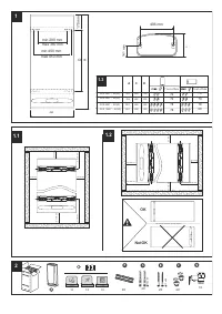
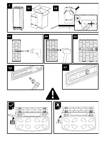
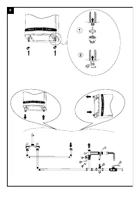
When mounted on a wall - the device is suspended by means of the M8 bolts attached to
the housing, which are installed on brackets pre-mounted and levelled with the wall. The
load-bearing brackets and dowels for wall mounting are included in the kit.
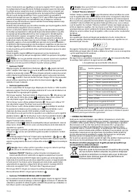
Vertical installation scheme - Fig. 4.1
Horizontal installation scheme – Fig. 4 2.
In order to prevent injury to the user and/or third persons in the event of faults in
the system for hot water supply, the appliance must be installed in premises
with floor hydro insulation and drainage to the sewerage. Under no circumstances
should you place objects which are not waterproof under the appliance. If the
appliance is installed in premises without floor hydro insulation, a protective tub with
drainage to the sewerage must be in place under the appliance.
Note:
The set does not include a protective tub and it should be chosen/
purchased by the user.
2.
Connecting the water heater to the water supply system
Fig. 5
Where: 1 - Inlet pipe; 2 - safety valve; 3 - reducing valve (for pressure in the water mains
higher than 0.6 MPa); 4 - stop valve; 5 - funnel connected to the sewerage; 6 – hose; 7 –
drain water tap.
Upon connecting the water heater to the water mains you must consider the indicative
colour markings (rings) affixed to the pipes: blue for cold (incoming) water, red for hot
(outgoing) water.
The mounting of the safety return-valve supplied with the water heater is
obligatory. The safety return-valve must be mounted on the cold water supply
pipe, in accordance with the direction of the arrow stamped on its body, indicating the
direction of the incoming water.
Exception:
If the local regulations (norms) require the use of another protection
valve or device (which conforms to EN 1487 or EN 1489), then it must be
purchased additionally. For device operating in accordance with EN 1487 the declared
maximum operational pressure must be no more than 0.7 MPa. For other protection
valves, the pressure at which they are calibrated must be 0.1 MPa lower than the one
marked on the appliance’s plate. In these cases the safety valve which the appliance is
supplied with should not be used.
Other type of stopping armature is not allowed between the protection return
valve (the protective device) and the appliance.
The presence of other (old) safety return-valves may lead to a breakdown of
your appliance and they must be removed.
The attaching of the safety return-valve to threads longer than 10 mm is not
allowed; otherwise this may damage the valve and therefore pose danger to
your appliance.
The safety-return valve and the pipe between the valve and the water heater
must be protected from freezing. In case of hose draining its free end must be
always open to the atmosphere (not to be immersed). Make sure that the hose is also
protected from freezing.
To fill the water heater with water first open the hot-water tap of the water-mixing
faucet. Then open the cold-water tap of the water-mixing faucet. The appliance is
full when a constant stream of water flows from the water-mixing faucet. Then close
the hot water tap.
When you have to empty the water heater, first you must cut off its power supply.
Then stop feeding water to the appliance. Open the hot-water tap of the water-
mixing faucet. Open tap 7 (fig. 5) in order to drain the water from water tank. If there
is no such tap built in the pipeline, than the water can be drained directly from the inlet
pipe of the water tank, having it disconnected from the water mains prior to this
When removing the flange, it is normal for several litres of water, which have
remained in the water tank, to be discharged.
Measures must be taken to prevent damages by the discharged water.
If the pressure in the water mains piping exceeds the value specified in paragraph I
above, a pressure-reducing valve must be installed, otherwise the water heater will
not be correctly operated. The manufacturer will not bear any liability for problems
arising from improper operation of the appliance.
3.
Connecting the water heater to the electrical mains
Make sure the appliance is full of water before switching on the electrical power
supply.
3.1.
For models with a power cord with a plug, connection to the electrical
mains is done by inserting the plug into an electrical socket.
Disconnection from the electrical mains is done by unplugging the power cord from
the socket.
The electrical socket must be properly connected to a separate current loop that
is provided with a safety fuse. It must be earthed.
3.2.
Water heaters with a power supply cord without a plug
The appliance has to be connected to a separate current loop of the stationary
electrical installation, and also it has to be provided with a safety fuse with nominal
current of 16A (20A for power > 3700W). The connection has to be permanent –
with no plug connectors. The current loop has to be provided with a safety fuse
and with an inbuilt device which would disconnect all poles in case of category III
overvoltage.
The connecting of the conductors of the supply cord of the appliance has to be
carried out in the following way:
•
conductor with brown insulation – to the phase conductor of the electrical
installation (L)
•
conductor with blue insulation – to the neutral conductor of the electrical
installation (N)
•
conductor with yellow-green insulation – to the safety conductor of the
electrical installation (
)
3.3.
Water heaters without power cord
The appliance has to be connected to a separate current loop of the stationary
electrical installation, provided with a safety fuse with nominal current of 16A (20A for
power > 3700W). Connection is done using copper single core (rigid) conductors –
cable 3 x 2.5 mm² for a total power of 3000W (cable 3 x 4.0 mm² for power > 3700W).
In the electrical circuit providing power supply for the appliance there has to an
inbuilt device which would disconnect all poles in case of category III overvoltage.
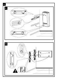
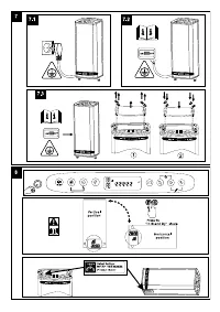
To install the power supply wire to the water heater, remove the plastic cover
(Fig.7.3).
Connect the power supply wire in compliance with the marking on the terminals, as
it follows:
•
the phase – to marking A or A1, L or L1;
•
the neutral – to marking N (B or B1 or N1)
•
The safety wire must be connected to the screw joint marked with
After installation, put the plastic cover back in its place!
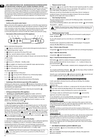
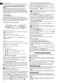
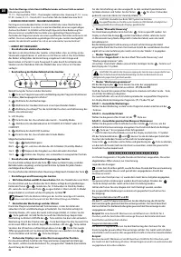
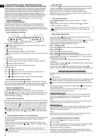
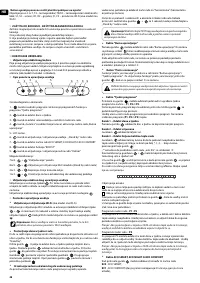
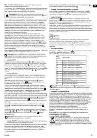
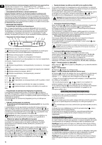
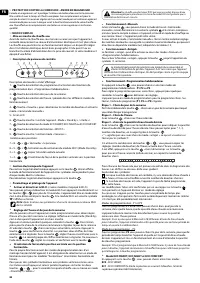
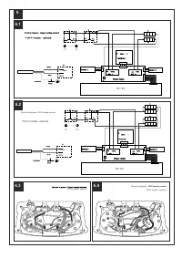
Explanations to Fig. 6:
T1, T2 - thermal circuit breaker; TR/EC - thermal regulator/ electronic control; R1, R2 –
heating element; F1, F2 - flange; S1, S2 - sensor; Wi-Fi module
(for models with Wi-Fi)
Характеристики

Остались вопросы?Не нашли свой ответ в руководстве или возникли другие проблемы? Задайте свой вопрос в форме ниже с подробным описанием вашей ситуации, чтобы другие люди и специалисты смогли дать на него ответ. Если вы знаете как решить проблему другого человека, пожалуйста, подскажите ему :)
