
Винные шкафы Liebherr WTI 2050 - инструкция пользователя по применению, эксплуатации и установке на русском языке. Мы надеемся, она поможет вам решить возникшие у вас вопросы при эксплуатации техники.
Если остались вопросы, задайте их в комментариях после инструкции.
"Загружаем инструкцию", означает, что нужно подождать пока файл загрузится и можно будет его читать онлайн. Некоторые инструкции очень большие и время их появления зависит от вашей скорости интернета.
u
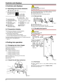
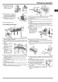
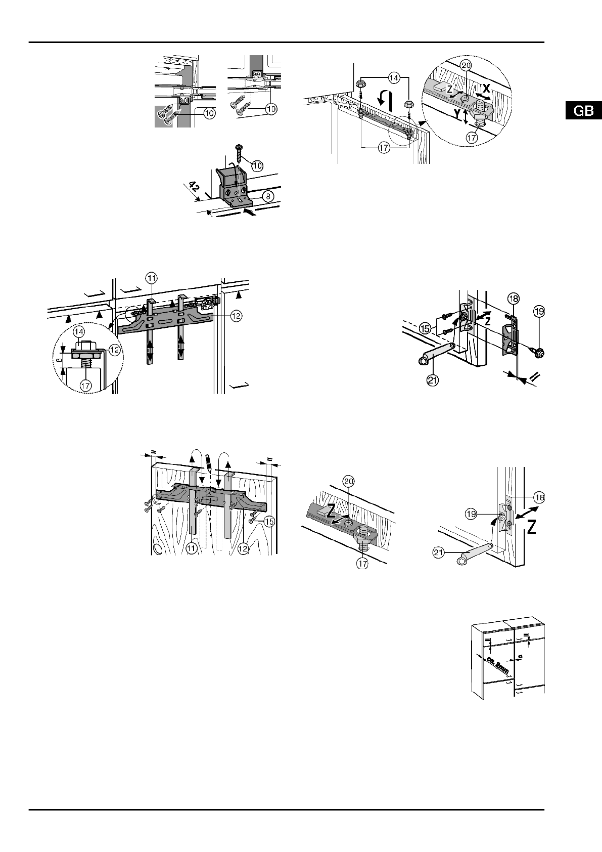
by screwing long Spax
screws
Fig. 20 (10)
through the top and
bottom hinge plates.
Fig. 20
u
Pre-assemble by passing a
long screw
Fig. 21 (8)through
the centre of the oblong hole in
the plastic bracket
Fig. 21 (10) .
u
Fold down the cover of the
plastic bracket
Fig. 21 (8).
Fig. 21
u
Close the appliance door.
4.2.2 Fitting the unit doors
Fig. 22
u
Check 8 mm presetting. (Distance between appliance door
and lower edge of crosspiece)
u
Push up assembly aids
Fig. 22 (11) to unit door height. Lower
edge ▲of the assembly aid = top edge of the unit door to be
fitted.
u
Unscrew fastening
crosspiece
Fig. 23 (12) by
undoing the locknuts
Fig. 22 (14).
u
Attach the fastening
crosspiece
Fig. 23 (12)using the
assembly
aids
Fig. 23 (11) to the
inside of the unit door.
Fig. 23
u
Centre the fastening crosspiece
Fig. 23 (12): mark a short
centre line on the unit door and put the tip of the arrow on the
crosspiece above it.
w
Distances to the outer edge are equal at the left and right.
For chipboard doors:
u
secure fastening crosspiece
Fig. 23 (12) with at least 6
screws.
For frame and panel doors:
u
secure fastening crosspiece
Fig. 23 (12) with 4 screws at the
edge.
u
Raise the assembly aids
Fig. 23 (11) for removal, turn them
and insert them into the adjacent openings.
Fig. 24
u
Attach the unit door to the adjusting bolts
Fig. 24 (17) and
loosely screw the locknuts
Fig. 24 (14) onto them.
u
Close the door.
u
Check the gap between the door and the surrounding unit
doors.
u
To laterally align the unit door: move the unit door in the X
direction.
u
To align the unit door in height Y and in lateral inclination:
adjust the adjusting bolt
Fig. 24 (17) with a screwdriver.
w
The unit door is flush and in alignment with the surrounding
unit fronts.
u
Tighten the locknuts
Fig. 24 (14).
u
Screw
mounting
bracket
Fig. 25 (18)
with hexagon screw
Fig. 25 (19) into the
pilot holes in the
appliance door.
Fig. 25
Ensure that both metal edges are flush (symbol //):
u
Drill pilot holes in the door of the unit (possibly make prelimi-
nary hole with a bradawl).
u
Screw the appliance door to the unit door with screws
Fig. 25 (15) passed through the mounting brackets
Fig. 25 (18).
Fig. 26
u
To align the unit door in depth Z: undo screws
Fig. 26 (20) at
the top, hexagon screws
Fig. 26 (19) at the door, then move
the door.
u
Allow an air gap of approx. 2 mm between
the unit door and the body of the unit.
Do not allow knobs and sealing lips to
contact the door - important for function!
For large or sectioned unit doors:
u
fit a 2nd pair of mounting brackets
Fig. 25 (18).
u
Use the holes pre-drilled in the handle
area of the appliance door for this
purpose.
Putting into operation
7
Характеристики

Остались вопросы?Не нашли свой ответ в руководстве или возникли другие проблемы? Задайте свой вопрос в форме ниже с подробным описанием вашей ситуации, чтобы другие люди и специалисты смогли дать на него ответ. Если вы знаете как решить проблему другого человека, пожалуйста, подскажите ему :)


