
Винные шкафы Liebherr WTI 2050 - инструкция пользователя по применению, эксплуатации и установке на русском языке. Мы надеемся, она поможет вам решить возникшие у вас вопросы при эксплуатации техники.
Если остались вопросы, задайте их в комментариях после инструкции.
"Загружаем инструкцию", означает, что нужно подождать пока файл загрузится и можно будет его читать онлайн. Некоторые инструкции очень большие и время их появления зависит от вашей скорости интернета.
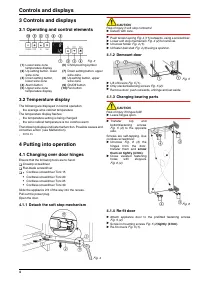
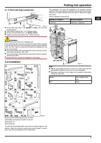
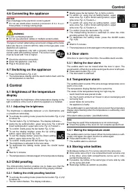
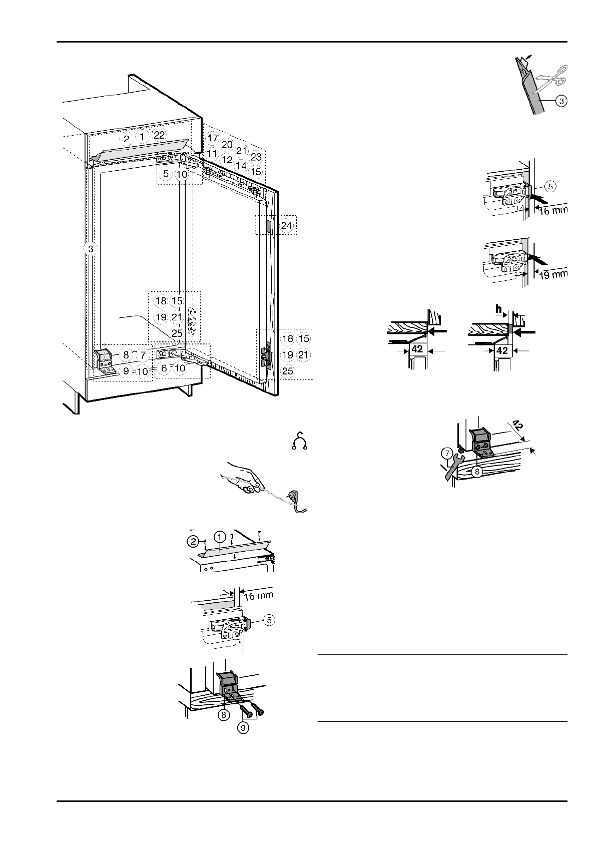
4.2.1 Installing the appliance
Fig. 10
u
Detach the connecting cable from the rear of the appli-
ance, removing the cable holder because otherwise
there will be vibratory noise!
u
Lay the connecting cable with
the help of a string in such a way
that the appliance can be easily
connected after fitting.
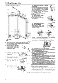
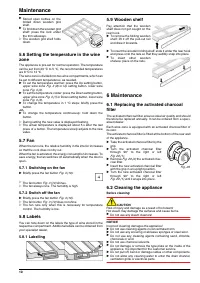
Fig. 11
u
Fit equaliser trim
Fig. 12 (1)
with screws
Fig. 12 (2) onto
the appliance.
Fig. 12
u
Slide the appliance 2/3 of the way into the recess.
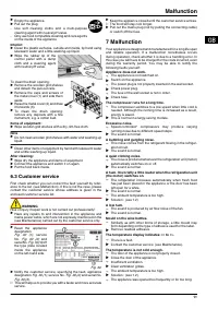
For 16 mm thick unit walls =
568 mm wide recess:
u
Clip spacer
Fig. 13 (5) and
spacer
Fig. 10 (6) onto the
hinges.
Fig. 13
u
Screw plastic bracket
Fig. 14 (8) onto the handle
side of the appliance with
M5 screws
Fig. 14 (9).
Fig. 14
For 16 mm thick unit walls = 568 mm
wide recess:
u
Remove the protective film from the cover
trim
Fig. 15 (3). Apply the strip on the side
wall of the appliance on the handle side
and flush with the front and glue on.
u
If necessary, shorten the cover trim
Fig. 15 (3) at the bottom.*
Fig. 15
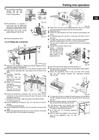
To slide in and align the appliance:
u
Slide in the appliance.
For 16 mm thick unit walls =
568 mm wide recess:
u
Let the spacers abut the side
wall of the unit.
Fig. 16
For 19 mm thick unit walls =
562 mm wide recess:
u
Align the front edges of the
hinges so as to be flush with the
side wall of the unit.
Fig. 17
Fig. 18
In case of units with (16 mm and 19 mm) door stop
components (knobs, sealing lips etc.):
u
To allow for the extra distance (depth of door stop compo-
nents): allow the hinges to protrude by the extra distance.
Fig. 19
For units without door stop components:
u
Align the plastic bracket in depth so as to be flush with the front
side of the side walls of the unit.
For units with door stop components:
u
To allow for the extra distance : align the plastic bracket
parallel to the front edge of the hinges.
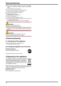
For units with set back base:
u
Align plastic bracket
Fig. 19 (8) in depth so as to be flush with
the front edges of the side walls of the unit, even if the bracket
projects over the base of the unit as a result.
u
Level the appliance by means of the adjustable feet using the
accompanying spanner
Fig. 19 (7).
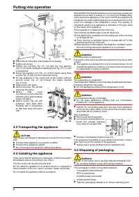
w
The appliance is now correctly positioned in depth. The
distance between the front edge of the side wall of the unit and
the body of the appliance is 42 mm all the way round (Allow
for door stop components, such as knobs and sealing lips.)
Note
Incorrect installation will lead to malfunction!
If the distance is not kept, the door may not close. This may lead
to icing, to condensate forming and to malfunction.
u
Be sure to keep to a spacing of 42 mm all the way round. (Allow
for door stop components, such as knobs and sealing lips.)
Fasten the appliance in the recess with screws:
Putting into operation
6
Характеристики

Остались вопросы?Не нашли свой ответ в руководстве или возникли другие проблемы? Задайте свой вопрос в форме ниже с подробным описанием вашей ситуации, чтобы другие люди и специалисты смогли дать на него ответ. Если вы знаете как решить проблему другого человека, пожалуйста, подскажите ему :)


