
Триммеры Stiga SBC 500 AE 278200008/ST1 - инструкция пользователя по применению, эксплуатации и установке на русском языке. Мы надеемся, она поможет вам решить возникшие у вас вопросы при эксплуатации техники.
Если остались вопросы, задайте их в комментариях после инструкции.
"Загружаем инструкцию", означает, что нужно подождать пока файл загрузится и можно будет его читать онлайн. Некоторые инструкции очень большие и время их появления зависит от вашей скорости интернета.


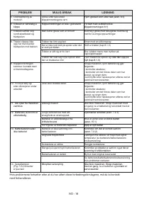


EN - 10
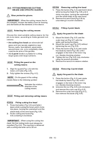
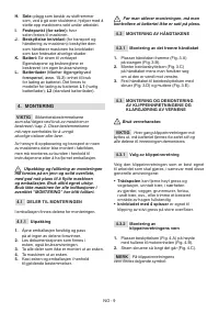
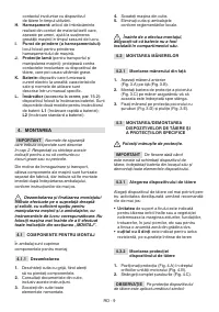
4.3 FITTING/REMOVING CUTTING
MEANS AND SPECIFIC GUARDS
Wear protective gloves.
IMPORTANT
When the cutting means has to
be changed, remove the battery from its housing
and dismantle all the elements of the device.
4.3.1 Selecting the cutting means
Choose the most suitable cutting means for the
job to be done, according to these general indi
-
cations:
•
the cutting line head
can eliminate tall
grass and non-woody vegetation near
fences, walls, foundations, pavements,
around trees, etc. or to completely clean
a particular area of the garden;
•
the
4
-
point
blade is suitable for cutting
tough grass over large surfaces.
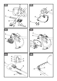
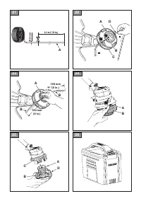
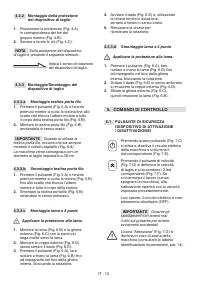
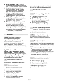
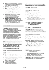
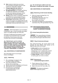
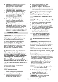
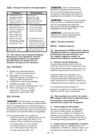
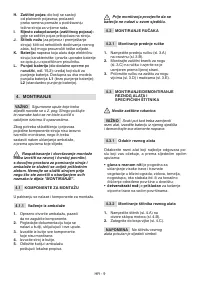
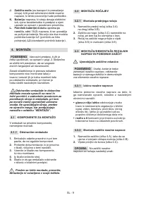
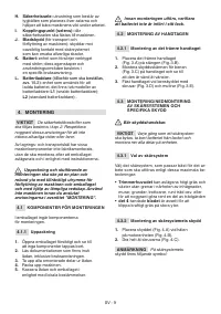
4.3.2 Fitting the guard on the
cutting means
1.
Align the guard (Fig. 4.A) with the
motor unit holes (Fig. 4.B).
2.
Fully tighten the screws (Fig. 4.C).
NOTE
On the guard of the cutting
means there is the following symbol:
Indicates the rotation
direction of the
cutting means.
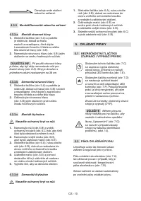
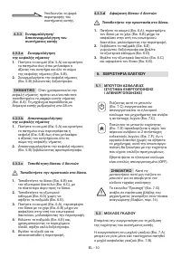
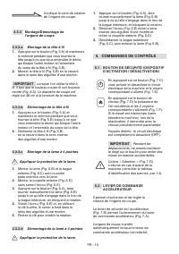
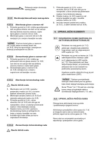
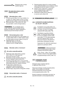
4.3.3 Fitting and removing cutting means
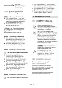
4.3.3.a
Fitting cutting line head
1.
Press the button (Fig. 5.A) and hold it
down while turning the head until it clicks
into place, locking the crankshaft and the
whole body of the wire head (Fig. 5.B).
2.
Fit the cutting line head (Fig.
5.B) screwing it clockwise.
IMPORTANT
When using the cutting line
head, the line cutting knife must always be
installed (Fig. 8.A). The machine is delivered
with a cutting diameter set to 38 cm.
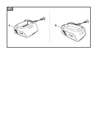
4.3.3.b
Removing cutting line head
1.
Press the button (Fig. 5.A) and hold it down
while turning the head (Fig. 5.B) until it
clicks into place, locking the crankshaft
and the whole body of the wire head.
2.
Remove the wire head (Fig.5.B) by
unscrewing it counter clockwise.
4.3.3.c
Fitting 4-point blade
Apply the guard to the blade.
1.
Mount the blade (Fig. 6.E) and the
outer ring-nut (Fig. 6.F) with the
wider part facing the blade.
2.
Mount the outer cup (Fig. 6.D) without
tightening the nut (Fig. 6.E).
3.
Press the button (Fig. 6.A) and rotate
the blade by hand (Fig. 6.B) until it
engages in the hole in the inner ring
nut, thereby blocking rotation.
4.
Tighten the nut (Fig. 6.E) fully clockwise
using the wrench provided.
5.
Remove the wrench to restore rotation.
4.3.3.d
Removing 4-point blade
Apply the guard to the blade.
1.
Press the button (Fig. 6.A) and rotate
the blade by hand (Fig. 6.B) until it
engages in the hole in the inner ring
nut, thereby blocking rotation.
2.
Unscrew the nut (Fig. 6.E) anti-clockwise
and remove the outer cup (Fig. 6.D).
3.
Remove the outer lock ring (Fig. 6.C),
then remove the blade (Fig. 6.B).
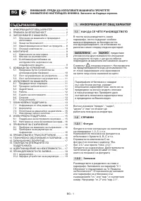
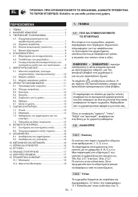
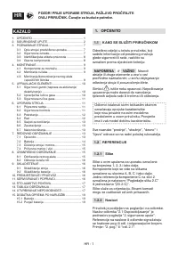
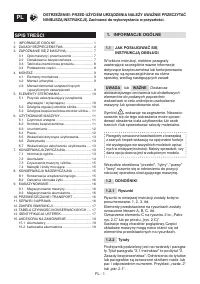
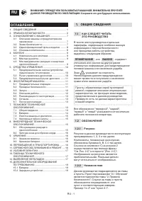
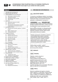
Содержание
- 464 ОБЩИЕ СВЕДЕНИЯ; ОГЛАВЛЕНИЕ
- 467 Ограничения в применении
- 468 Во время наладки машины; Хранение
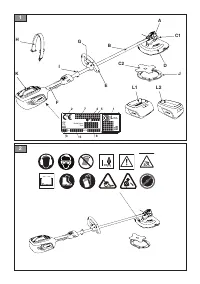
- 470 ОЗНАКОМЛЕНИЕ С МАШИНОЙ
- 472 МОНТАЖ; Выбор режущего приспособления; На защите режущего
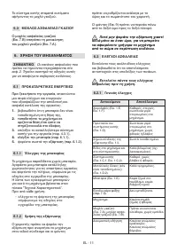
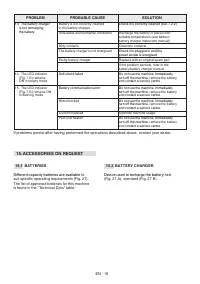
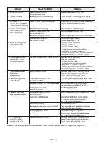
- 473 СРЕДСТВА УПРАВЛЕНИЯ; Световые индикаторы не горят:
- 474 ЭКСПЛУАТАЦИЯ МАШИНЫ
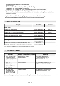
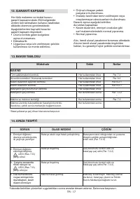
- 476 ПЛАНОВОЕ ТЕХНИЧЕСКОЕ
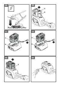
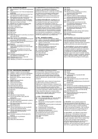
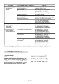
- 477 БАТАРЕЯ; ПРИМЕЧАНИЕ; Повторная установка
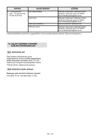
- 479 ЗАТОЧКА НОЖА ДЛЯ ОБРЕЗКИ КОРДА; ХРАНЕНИЕ; ХРАНЕНИЕ МАШИНЫ; ПЕРЕМЕЩЕНИЕ И
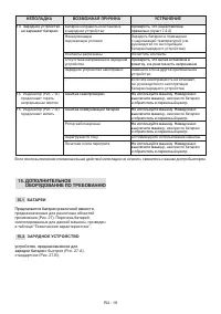
- 482 ДОПОЛНИТЕЛЬНОЕ; БАТАРЕИ; ЗАРЯДНОЕ УСТРОЙСТВО


