Преобразователи частоты Danfoss VLT HVAC Basic - инструкция пользователя по применению, эксплуатации и установке на русском языке. Мы надеемся, она поможет вам решить возникшие у вас вопросы при эксплуатации техники.
Если остались вопросы, задайте их в комментариях после инструкции.
"Загружаем инструкцию", означает, что нужно подождать пока файл загрузится и можно будет его читать онлайн. Некоторые инструкции очень большие и время их появления зависит от вашей скорости интернета.
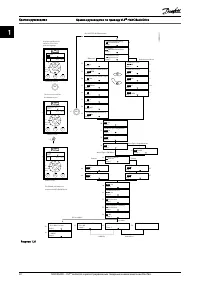
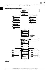
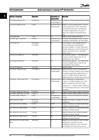
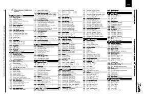
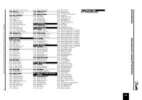

1.5.1 Структура главного
меню
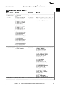
0-**
Operation / Display
0-0*
Basic Settings
0-01
Language
0-03
Regional Settings
0-04
Operating State at Power-up
0-06
GridType
0-07
Auto DC Braking
0-1*
Set-up Operations
0-10
Active Set-up
0-11
Programming Set-up
0-12
Link Setups
0-3*
LCP Custom Readout
0-30
Custom Readout Unit
0-31
Custom Readout Min Value
0-32
Custom Readout Max Value
0-37
Display Text 1
0-38
Display Text 2
0-39
Display Text 3
0-4*
LCP Keypad
0-40
[Hand on] Key on LCP
0-42
[Auto on] Key on LCP
0-44
[Off/Reset] Key on LCP
0-5*
Copy/Save
0-50
LCP Copy
0-51
Set-up Copy
0-6*
Password
0-60
Main Menu Password
1-**
Load and Motor
1-0*
General Settings
1-00
Configuration Mode
1-01
Motor Control Principle
1-03
Torque Characteristics
1-06
Clockwise Direction
1-1*
Motor Selection
1-10
Motor construction
1-14
Damping Gain
1-15
Low Speed Filter Time Const
1-16
High Speed Filter Time Const
1-17
Voltage filter time const
1-2*
Motor Data
1-20
Motor Power
1-22
Motor Voltage
1-23
Motor Frequency
1-24
Motor Current
1-25
Motor Nominal Speed
1-26
Motor Cont. Rated Torque
1-29
Automatic Motor Adaption (AMA)
1-3*
Adv. Motor Data
1-30
Stator Resistance (Rs)
1-33
Stator Leakage Reactance (X1)
1-35
Main Reactance (Xh)
1-37
d-axis Inductance (Ld)
1-39
Motor Poles
1-4*
Adv. Motor Data II
1-40
Back EMF at 1000 RPM
1-42
Motor Cable Length
1-43
Motor Cable Length Feet
1-5*
Load Indep. Setting
1-50
Motor Magnetisation at Zero Speed
1-52
Min Speed Normal Magnetising [Hz]
1-55
U/f Characteristic - U
1-56
U/f Characteristic - F
1-6*
Load Depen. Setting
1-60
Low Speed Load Compensation
1-61
High Speed Load Compensation
1-62
Slip Compensation
1-63
Slip Compensation Time Constant
1-64
Resonance Dampening
1-65
Resonance Dampening Time Constant
1-66
Min. Current at Low Speed
1-7*
Start Adjustments
1-71
Start Delay
1-72
Start Function
1-73
Flying Start
1-8*
Stop Adjustments
1-80
Function at Stop
1-82
Min Speed for Function at Stop [Hz]
1-9*
Motor Temperature
1-90
Motor Thermal Protection
1-93
Thermistor Source
2-**
Brakes
2-0*
DC-Brake
2-00
DC Hold/Motor Preheat Current
2-01
DC Brake Current
2-02
DC Braking Time
2-04
DC Brake Cut In Speed
2-06
Parking Current
2-07
Parking Time
2-1*
Brake Energy Funct.
2-10
Brake Function
2-16
AC brake Max. Current
2-17
Over-voltage Control
3-**
Reference / Ramps
3-0*
Reference Limits
3-02
Minimum Reference
3-03
Maximum Reference
3-1*
References
3-10
Preset Reference
3-11
Jog Speed [Hz]
3-14
Preset Relative Reference
3-15
Reference 1 Source
3-16
Reference 2 Source
3-17
Reference 3 Source
3-4*
Ramp 1
3-41
Ramp 1 Ramp Up Time
3-42
Ramp 1 Ramp Down Time
3-5*
Ramp 2
3-51
Ramp 2 Ramp Up Time
3-52
Ramp 2 Ramp Down Time
3-8*
Other Ramps
3-80
Jog Ramp Time
3-81
Quick Stop Ramp Time
4-**
Limits / Warnings
4-1*
Motor Limits
4-10
Motor Speed Direction
4-12
Motor Speed Low Limit [Hz]
4-14
Motor Speed High Limit [Hz]
4-18
Current Limit
4-19
Max Output Frequency
4-4*
Adj. Warnings 2
4-40
Warning Freq. Low
4-41
Warning Freq. High
4-5*
Adj. Warnings
4-50
Warning Current Low
4-51
Warning Current High
4-54
Warning Reference Low
4-55
Warning Reference High
4-56
Warning Feedback Low
4-57
Warning Feedback High
4-58
Missing Motor Phase Function
4-6*
Speed Bypass
4-61
Bypass Speed From [Hz]
4-63
Bypass Speed To [Hz]
4-64
Semi-Auto Bypass Set-up
5-**
Digital In/Out
5-0*
Digital I/O mode
5-00
Digital Input Mode
5-03
Digital Input 29 Mode
5-1*
Digital Inputs
5-10
Terminal 18 Digital Input
5-11
Terminal 19 Digital Input
5-12
Terminal 27 Digital Input
5-13
Terminal 29 Digital Input
5-3*
Digital Outputs
5-34
On Delay, Digital Output
5-35
Off Delay, Digital Output
5-4*
Relays
5-40
Function Relay
5-41
On Delay, Relay
5-42
Off Delay, Relay
5-5*
Pulse Input
5-50
Term. 29 Low Frequency
5-51
Term. 29 High Frequency
5-52
Term. 29 Low Ref./Feedb. Value
5-53
Term. 29 High Ref./Feedb. Value
5-9*
Bus Controlled
5-90
Digital & Relay Bus Control
6-**
Analog In/Out
6-0*
Analog I/O Mode
6-00
Live Zero Timeout Time
6-01
Live Zero Timeout Function
6-1*
Analog Input 53
6-10
Terminal 53 Low Voltage
6-11
Terminal 53 High Voltage
6-12
Terminal 53 Low Current
6-13
Terminal 53 High Current
6-14
Terminal 53 Low Ref./Feedb. Value
6-15
Terminal 53 High Ref./Feedb. Value
6-16
Terminal 53 Filter Time Constant
6-19
Terminal 53 mode
6-2*
Analog Input 54
6-20
Terminal 54 Low Voltage
6-21
Terminal 54 High Voltage
6-22
Terminal 54 Low Current
6-23
Terminal 54 High Current
6-24
Terminal 54 Low Ref./Feedb. Value
6-25
Terminal 54 High Ref./Feedb. Value
6-26
Terminal 54 Filter Time Constant
6-29
Terminal 54 mode
6-7*
Analog/Digital Output 45
6-70
Terminal 45 Mode
6-71
Terminal 45 Analog Output
6-72
Terminal 45 Digital Output
6-73
Terminal 45 Output Min Scale
6-74
Terminal 45 Output Max Scale
6-76
Terminal 45 Output Bus Control
6-9*
Analog/Digital Output 42
6-90
Terminal 42 Mode
6-91
Terminal 42 Analog Output
6-92
Terminal 42 Digital Output
6-93
Terminal 42 Output Min Scale
6-94
Terminal 42 Output Max Scale
6-96
Terminal 42 Output Bus Control
6-98
Drive Type
8-**
Comm. and Options
8-0*
General Settings
8-01
Control Site
8-02
Control Source
8-03
Control Timeout Time
8-04
Control Timeout Function
8-3*
FC Port Settings
8-30
Protocol
8-31
Address
8-32
Baud Rate
8-33
Parity / Stop Bits
8-35
Minimum Response Delay
8-36
Maximum Response Delay
8-37
Maximum Inter-char delay
8-4*
FC MC protocol set
8-43
PCD Read Configuration
8-5*
Digital/Bus
8-50
Coasting Select
8-51
Quick Stop Select
8-52
DC Brake Select
8-53
Start Select
8-54
Reversing Select
8-55
Set-up Select
8-56
Preset Reference Select
8-7*
BACnet
8-70
BACnet Device Instance
8-72
MS/TP Max Masters
8-73
MS/TP Max Info Frames
8-74
"I am" Service
8-75
Intialisation Password
8-8*
FC Port Diagnostics
8-80
Bus Message Count
8-81
Bus Error Count
8-82
Slave Messages Rcvd
8-83
Slave Error Count
8-84
Slave Messages Sent
8-85
Slave Timeout Errors
8-88
Reset FC port Diagnostics
8-9*
Bus Feedback
8-94
Bus Feedback 1
13-** Smart Logic
13-0* SLC Settings
13-00 SL Controller Mode
13-01 Start Event
13-02 Stop Event
13-03 Reset SLC
13-1* Comparators
13-10 Comparator Operand
13-11 Comparator Operator
13-12 Comparator Value
13-2* Timers
13-20 SL Controller Timer
13-4* Logic Rules
13-40 Logic Rule Boolean 1
13-41 Logic Rule Operator 1
13-42 Logic Rule Boolean 2
13-43 Logic Rule Operator 2
13-44 Logic Rule Boolean 3
13-5* States
13-51 SL Controller Event
13-52 SL Controller Action
14-** Special Functions
14-0* Inverter Switching
14-01 Switching Frequency
14-03 Overmodulation
14-08 Damping Gain Factor
14-1* Mains On/Off
14-10 Mains Failure
14-12 Function at Mains Imbalance
14-2* Reset Functions
14-20 Reset Mode
14-21 Automatic Restart Time
14-22 Operation Mode
14-23 Typecode Setting
14-27 Action At Inverter Fault
14-28 Production Settings
14-29 Service Code
14-4* Energy Optimising
14-40 VT Level
14-41 AEO Minimum Magnetisation
14-5* Environment
14-50 RFI Filter
14-51 DC-Link Voltage Compensation
14-52 Fan Control
14-53 Fan Monitor
14-55 Output Filter
14-6* Auto Derate
14-63 Min Switch Frequency
15-** Drive Information
15-0* Operating Data
15-00 Operating hours
15-01 Running Hours
15-02 kWh Counter
15-03 Power Up's
15-04 Over Temp's
15-05 Over Volt's
15-06 Reset kWh Counter
Краткое руководство
Краткое руководство по приводу VLT
®
HVAC Basic Drive
32
MG18A450 – VLT
®
является зарегистрированным товарным знаком компании Danfoss
1
1
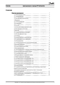
Содержание
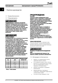
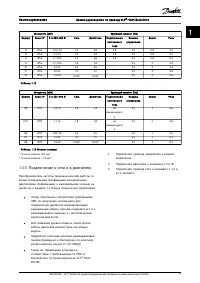
- 3 Краткое руководство; Техника безопасности; Предупреждение о высоком напряжении; Время разрядки; Напряжение; ПРЕДУПРЕЖДЕНИЕ; Ток утечки на землю превышает 3,5 мА.
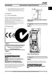
- 4 Сеть ИТ; Болт ЭМС; ], если в работе используется питания от сети ИТ.; Краткое руководство
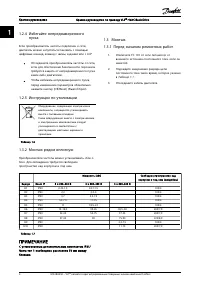
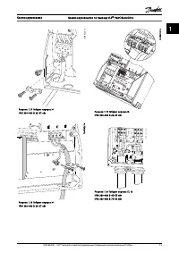
- 5 пуска; Отсоедините кабель двигателя.; Свободное пространство над; ПРИМЕЧАНИЕ
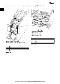
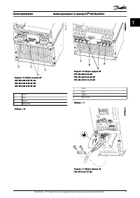
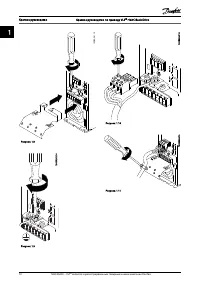
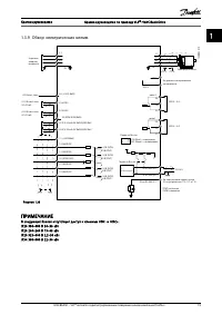
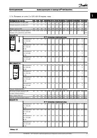
- 7 электромонтажу
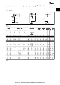
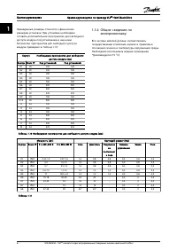
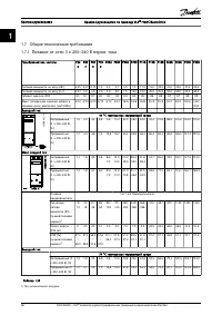
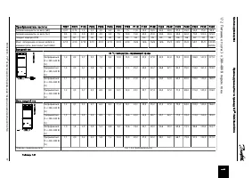
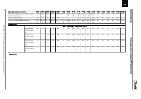
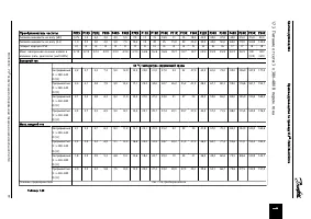
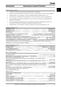
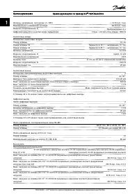
- 8 Общие технические требования
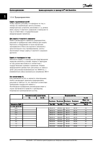
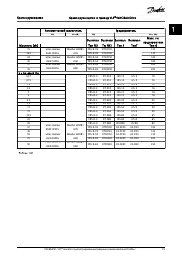
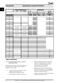
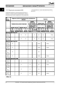
- 17 Таблица 1.22 Предохранители; требований ЭМС
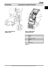
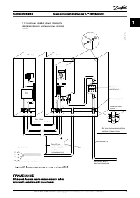
- 18 Рисунок 1.21 Электрический монтаж с учетом требований ЭМС
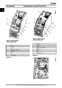
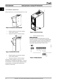
- 19 Рисунок 1.22 Расположение клемм управления; -00 Digital Input Mode; Рисунок 1.25 Клеммы управления
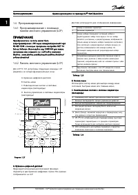
- 21 Программирование; softwaredownload; Дисплей используется для отображения информации.
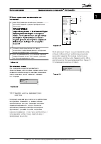
- 22 Цифровой вход клеммы 27 (; контура
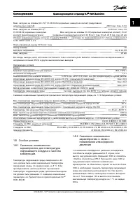
- 25 -29 Automatic Motor Adaption
- 27 Мастер настройки параметров замкнутого контура
- 31 до 0
- 35 Предупреждения и аварийные сигналы
- 36 Limit
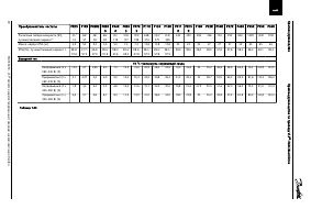
- 37 Общие технические требования; ) При номинальной нагрузке
- 38 Преобразователь частоты; Габарит корпуса IP20; C температура окружающей среды; Плавкие предохранители
- 39 Выходной ток
- 40 Габарит корпуса IP54
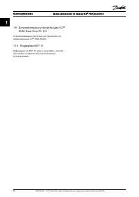
- 46 Руководство по проектированию; характеристик в связи с
- 47 О дополнительных устройствах см.


