
Перфораторы Bosch GBH 240F - инструкция пользователя по применению, эксплуатации и установке на русском языке. Мы надеемся, она поможет вам решить возникшие у вас вопросы при эксплуатации техники.
Если остались вопросы, задайте их в комментариях после инструкции.
"Загружаем инструкцию", означает, что нужно подождать пока файл загрузится и можно будет его читать онлайн. Некоторые инструкции очень большие и время их появления зависит от вашей скорости интернета.


English |
15
Bosch Power Tools
1 609 92A 3SE | (24.4.17)
Noise/Vibration Information
Sound emission values determined according to
EN 60745-2-6.
Typically the A-weighted noise levels of the product are:
Sound pressure level 92.5 dB(A); Sound power level
103.5 dB(A). Uncertainty K = 3 dB.
Wear hearing protection!
Vibration total values a
h
(triax vector sum) and uncertainty K
determined according to EN 60745-2-6:
Hammer drilling into concrete: a
h
= 13.1 m/s
2
, K = 1.5 m/s
2
Chiselling: a
h
= 13.9 m/s
2
, K = 1.5 m/s
2
The vibration level given in this information sheet has been
measured in accordance with a standardised test given in
EN 60745 and may be used to compare one tool with anoth-
er. It may be used for a preliminary assessment of exposure.
The declared vibration emission level represents the main ap-
plications of the tool. However if the tool is used for different
applications, with different accessories or insertion tools or is
poorly maintained, the vibration emission may differ. This
may significantly increase the exposure level over the total
working period.
An estimation of the level of exposure to vibration should also
take into account the times when the tool is switched off or
when it is running but not actually doing the job. This may sig-
nificantly reduce the exposure level over the total working
period.
Identify additional safety measures to protect the operator
from the effects of vibration such as: maintain the tool and the
accessories, keep the hands warm, organisation of work pat-
terns.
Assembly
Before any work on the machine itself, pull the mains
plug.
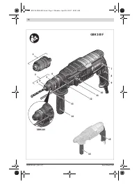
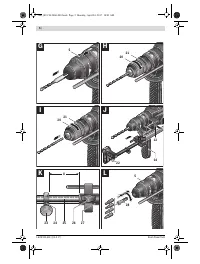
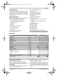
Auxiliary Handle
Operate your machine only with the auxiliary handle
14.
Changing the position of the auxiliary handle
(see figure A)
The auxiliary handle
14
can be set to any position for a secure
and low-fatigue working posture.
– Turn the bottom part of the auxiliary handle
14
in counter-
clockwise direction and swivel the auxiliary handle
14
to
the desired position. Then retighten the bottom part of the
auxiliary handle
14
by turning in clockwise direction.
Pay attention that the clamping band of the auxiliary
handle is positioned in the groove on the housing as
intended for.
Adjusting the Drilling Depth (see figure B)
The required drilling depth
X
can be set with the depth stop
13
.
– Press the button for the depth stop adjustment
12
and
insert the depth stop into the auxiliary handle
14
.
The knurled surface of the depth stop
13
must face down-
ward.
– Insert the SDS-plus drilling tool to the stop into the SDS-
plus tool holder
3
. Otherwise, the movability of the SDS-
plus drilling tool can lead to incorrect adjustment of the
drilling depth.
– Pull out the depth stop until the distance between the tip of
the drill bit and the tip of the depth stop corresponds with
the desired drilling depth
X
.
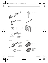
Selecting Drill Chucks and Tools
For hammer drilling and chiselling, SDS-plus tools are re-
quired that are inserted in the SDS-plus drill chuck.
For drilling without impact in wood, metal, ceramic and
plastic as well as for screwdriving, tools without SDS-plus are
used (e. g., drill bits with cylindrical shank). For these tools, a
keyless chuck or a key type drill chuck are required.
GBH 240 F: The SDS-plus quick change chuck
2
can easily be
replaced against the quick change keyless chuck
1
provided.
Changing the Key Type Drill Chuck (GBH 240)
To work with tools without SDS-plus (e. g., drills with cylindri-
cal shank), a suitable drill chuck must be mounted (key type
drill chuck or keyless chuck, accessories).
Mounting the Key Type Drill Chuck (see figure C)
– Screw the SDS-plus adapter shank
18
into a key type drill
chuck
17
. Secure the key type drill chuck
17
with the
securing screw
16
.
Please observe that the securing
screw has a left-hand thread.
Inserting the Key Type Drill Chuck (see figure C)
– Clean the shank end of the adapter shank and apply a light
coat of grease.
– Insert the key type drill chuck with the adapter shank into
the tool holder with a turning motion until it automatically
locks.
– Check the locking effect by pulling the key type drill chuck.
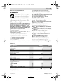
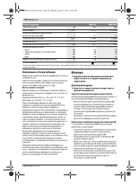
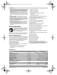
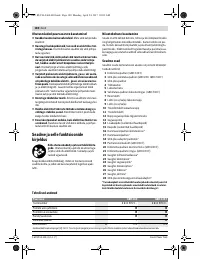
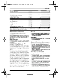
Drilling diameter, max.:
– Concrete
– Brickwork (with core bit)
– Steel
– Wood
mm
mm
mm
mm
24
68
13
30
24
68
13
30
Weight according to EPTA-Procedure 01:2014
kg
2.8
2.9
Protection class
/
II
/
II
Rotary Hammer
GBH 240
GBH 240 F
The values given are valid for a nominal voltage [U] of 230 V. For different voltages and models for specific countries, these values can vary.
OBJ_BUCH-2460-003.book Page 15 Monday, April 24, 2017 10:03 AM
Содержание
- 118 Указания по технике безопасности для
- 119 Описание продукта и услуг; Применение по назначению
- 120 Технические данные; Сборка; Дополнительная рукоятка
- 121 Выбор сверлильного патрона и инструмента
- 123 Работа с инструментом; Включение электроинструмента
- 124 Техобслуживание и сервис; Техобслуживание и очистка
Характеристики

Остались вопросы?Не нашли свой ответ в руководстве или возникли другие проблемы? Задайте свой вопрос в форме ниже с подробным описанием вашей ситуации, чтобы другие люди и специалисты смогли дать на него ответ. Если вы знаете как решить проблему другого человека, пожалуйста, подскажите ему :)


