Насосы Wilo HiMulti 3-45 P (4194284) - инструкция пользователя по применению, эксплуатации и установке на русском языке. Мы надеемся, она поможет вам решить возникшие у вас вопросы при эксплуатации техники.
Если остались вопросы, задайте их в комментариях после инструкции.
"Загружаем инструкцию", означает, что нужно подождать пока файл загрузится и можно будет его читать онлайн. Некоторые инструкции очень большие и время их появления зависит от вашей скорости интернета.


26
English
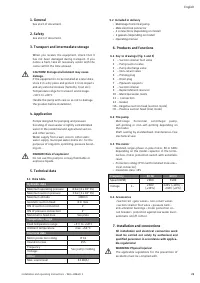
7.1 Upon receipt of the product
• Unpack the pump and recycle or dispose of the
packaging in an environmentally responsible
manner.
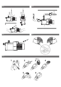
• Handling (Fig. 4).
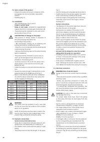
7.2 Installation
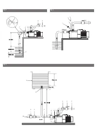
Two standard types (Fig. 1 and 3)
Pump in suction mode
Pump in inlet mode
connected to replenishment
reservoir (item 9) or municipal water mains (item 10).
• The pump must be installed in a dry, well-venti-
lated location free of frost.
CAUTION! Risk of damage to the pump!
The presence of foreign matter or impurities in
the pump housing may affect the
functioning of the product.
• We recommend carrying out all soldering and
brazing work before installing the pump.
• Rinse the circuit completely before installing and
commissioning the pump.
• Remove the blanking caps on the pump housing
before installation.
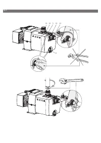
• The pump must be installed in a place easy to
reach, protected against frost and as close as
possible to the drawing point.
• To ensure access to the motor fan, allow a min-
imum distance of at least 0.3 m from the wall
behind the unit.
• Install the pump on a smooth and horizontal sur-
face.
• Secure the pump through 2 oblong holes on the
pedestal bearing (for Ø M8 fasteners) Fig. 7.
• Bear in mind that the altitude of the installation
site and the water temperature may reduce the
suction capacity of the pump.
WARNING!
The pump must be installed in such a way that
no one can touch the hot surfaces of the product
when it is in operation.
NOTE: As the pump may have been tested in the
factory, there may be some residual water in the
product. We recommend rinsing the pump.
7.3 Hydraulic connections
General connection instructions
• Screw the 2 connections manually (item 11) and
gasket (item 12) (depending on model) Fig. 9.
• Use flexible, braid-reinforced hose piping or rigid
piping.
• The pump must not bear the weight of the pipes
Fig. 5.
• Seal the piping well using appropriate products.
• Install a system of protection against low water
level to prevent dry running of the pump.
• Limit the length of the piping and avoid all fea-
tures that cause friction loss (tapers, elbows,
buckling etc.).
Suction connections
• The diameter of the suction pipe must never be
less than the port on the pump.
Furthermore, for pumps of the series 4 m³/h
which have negative suction head (HA) greater
than 6 m, we recommend piping of a diameter
greater than the nominal diameter (DN) of the
pump in order to limit friction loss.
• In the case of negative suction head, the pump
must be the highest point of the installation and
the suction piping must always be on a rising
gradient from the extraction point to the pump,
in order to prevent air bubbles forming in the
suction pipe.
•
Air must not be allowed to enter the suction
piping while the pump is in operation.
• Installing a suction strainer (max. cross-section
of holes: 2 mm) prevents damage to the pump
from the intake of particles.
• If the pump is installed with negative suction
head: submerge the suction strainer (min. 700
mm). Ballast the flexible hose piping if necessary.
7.4 Electrical connection
WARNING! Risk of electric shock!
Danger from electrical current must be eliminat-
ed.
• Have all electrical work carried out by a qualified
electrician only!
• Before any electrical connection is made, the
pump must be de-energised (switched off) and
protected against unauthorised restarting.
• To ensure safe installation and operation, the
unit must be earthed correctly with the earth ter-
minals of the power supply.
CAUTION!
An error in the electrical connection
will damage the motor.
The power cable must never touch the piping
or the pump, and must be kept away from any
moisture.
• See the motor’s rating plate for its electrical
characteristics (frequency, voltage, current).
• The single-phase motor of this pump has an
integrated motor protection switch.
• Power supply: use a cable conforming with appli-
cable standards (3 cores: 2 phases + earth):
H05RN-F 3 G 1.5 minimum
H05RN-F 3 G 2.5 maximum
• A damaged cable or connector must be replaced
by the corresponding part available from the
manufacturer or the manufacturer’s customer
service.
• The electrical connections must be established
by following the assembly diagram for the quick
connector (Fig. 8) and connecting it to the pump
(Fig. 6).
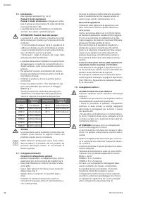
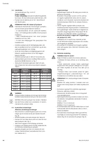
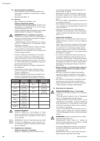
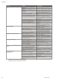
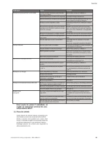
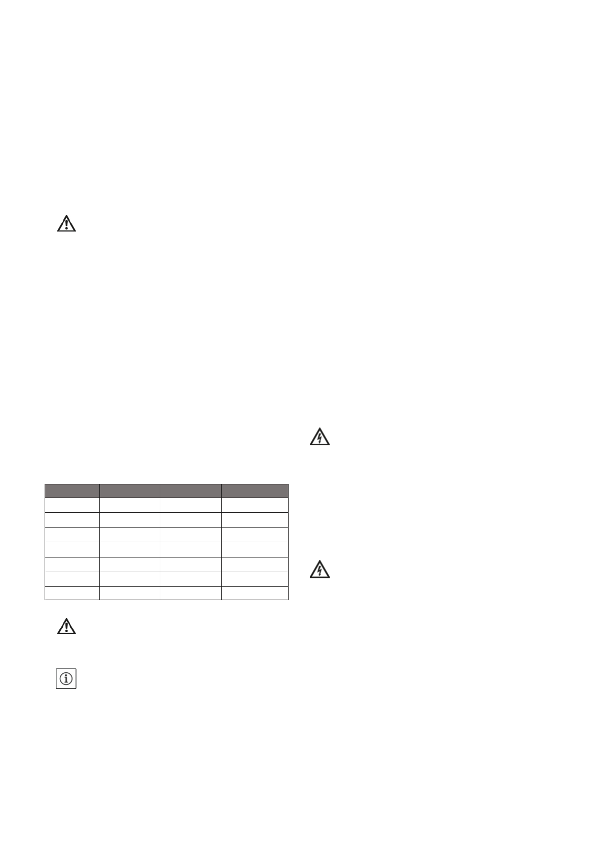
Altitude
Loss of head
Temperature Loss of head
0 m
0 m head
20°C
0,20 m head
500 m
0,60 m head
20°C
0,20 m head
1000 m
1,15 m head
20°C
0,20 m head
1500 m
1,70 m head
2000 m
2,20 m head
2500 m
2,65 m head
3000 m
3,20 m head
WILO SE 03/2021
Содержание
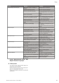
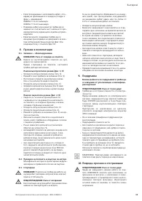
- 75 Русский; Гидравлические характеристики
- 77 Ввод в эксплуатацию; Проверка направления вращения двигателя; Техническое обслуживание; Все работы по техническому обслуживанию
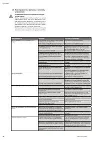
- 78 Неисправности, причины и способы; ОСТОРОЖНО! Опасность поражения электри
- 79 При невозможности самостоятельно; Информация о сборе бывших в употребле
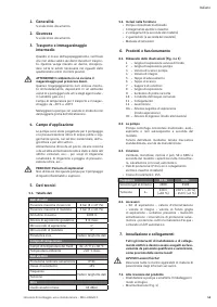
Характеристики

Остались вопросы?Не нашли свой ответ в руководстве или возникли другие проблемы? Задайте свой вопрос в форме ниже с подробным описанием вашей ситуации, чтобы другие люди и специалисты смогли дать на него ответ. Если вы знаете как решить проблему другого человека, пожалуйста, подскажите ему :)
