
Мультиметры BENNING MM 3 044029 - инструкция пользователя по применению, эксплуатации и установке на русском языке. Мы надеемся, она поможет вам решить возникшие у вас вопросы при эксплуатации техники.
Если остались вопросы, задайте их в комментариях после инструкции.
"Загружаем инструкцию", означает, что нужно подождать пока файл загрузится и можно будет его читать онлайн. Некоторые инструкции очень большие и время их появления зависит от вашей скорости интернета.


05/ 2020
BENNING MM 3
15
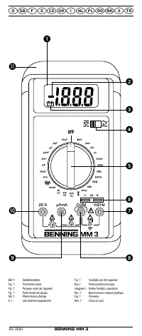
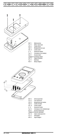
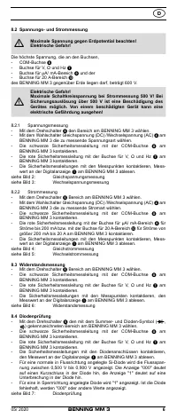
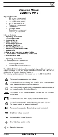
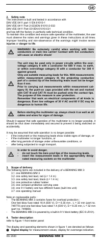
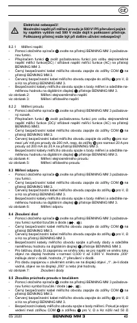
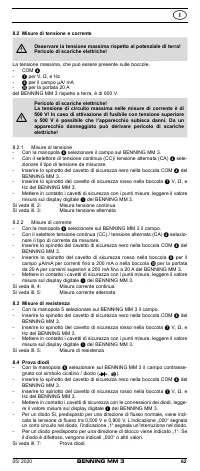
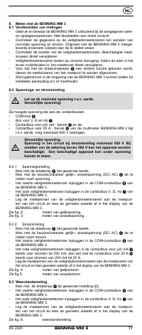
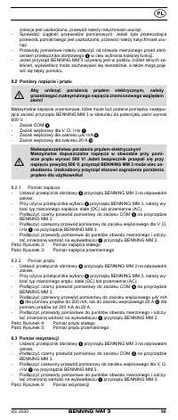
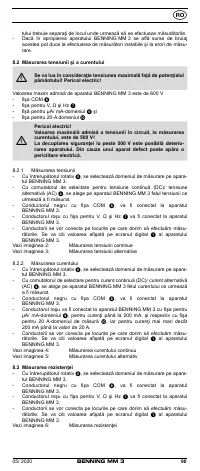
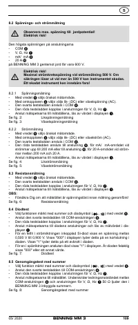
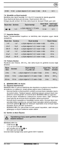
8.2 Voltage and current measurement
To avoid electrical shock, observe the maximum rated voltage
to earth ground!
The maximum rated voltage that should be applied between any of the following
terminals of the BENNING MM 3 and earth ground is 600 V.
- COM terminal
- Input terminal for V, Ω, and Hz
- Input terminal for µA/ mA range
- Input terminal for 20 A range
Electrical hazard! Maximum permissible circuit voltage for
current measurement is 500 V! If a safety fuse blows at a
voltage above 500 V the BENNING MM 3 could be damaged.
A damaged tester presents an electrical shock hazard to the
user!
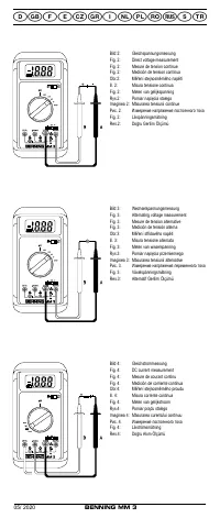
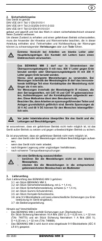
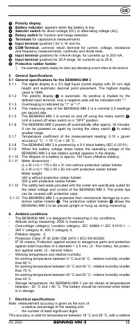
8.2.1 Voltage measurement
- Select the appropriate range with the rotary switch
of the BENNING MM 3.
- Use the selector switch
of the BENNING MM 3 to select the required
direct (DC) or alternating (AC) voltage to be measured.
- Connect the black safety test lead to the COM-terminal
of the
BENNING MM 3.
- Connect the red safety test lead to the input terminal for V, Ω, and Hz
of
the BENNING MM 3.
- Connect the safety test leads to the circuit measurement points and read
the measured value on the digital display
of the BENNING MM 3.
see Figure 2:
Direct voltage measurement
see Figure 3:
Alternating voltage measurement
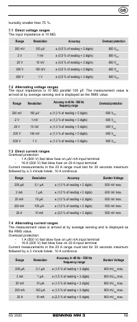
8.2.2 Current measurement
- Select the appropriate range with the rotary switch
of the BENNING MM 3.
- Use the selector switch
of the BENNING MM 3 to select the required
direct (DC) or alternating (AC) current to be measured.
- Connect the black safety test lead to the COM-terminal
of the
BENNING MM 3.
- Connect the red safety test lead to the input terminal for the µA/ mA range
for currents up to 200 mA, or to the input terminal for the 20 A range
for currents between 200 mA and 20 A of the BENNING MM 3.
- Connect the safety test leads to the circuit measurement points and read
the measured value on the digital display
of the BENNING MM 3.
see Figure 4:
DC current measurement
see Figure 5:
AC current measurement
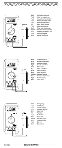
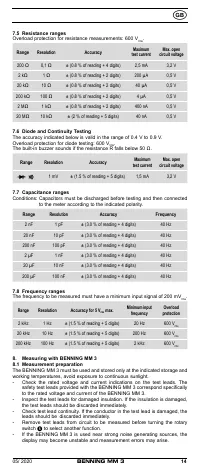
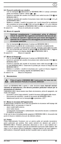
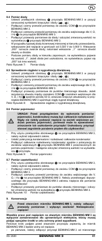
8.3 Resistance Measurement
- Select the appropriate range with the rotary switch
of the BENNING MM 3.
- Connect the black safety test lead to the COM-terminal
of the
BENNING MM 3.
- Connect the red safety test lead to the input terminal for V, Ω, and Hz
of
the BENNING MM 3.
- Connect the safety test leads to the circuit measurement points and read
the measured value on the digital display
of the BENNING MM 3.
see Figure 6:
Resistance measurement
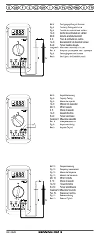
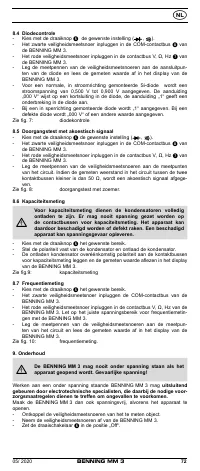
8.4 Diode Testing
- Turn the rotary switch
of the BENNING MM 3 to select the appropriate
range identified by a buzzer and diode symbol (
, ).
- Connect the black safety test lead to the COM-terminal
of the
BENNING MM 3.
- Connect the red safety test lead to the input terminal for V, Ω, and Hz
of
the BENNING MM 3.
- Connect the safety test leads across the diodes and read the measured
value on the digital display
of the BENNING MM 3.
- For a typical silicone diode tested in the forward-biased direction a voltage
flow between 0,500 V and 0,900 V is displayed. A display showing "000"
indicates a short circuit in the diode, whereas a display showing "1" indi-
cates an open circuit in the diode.
- For a diode tested in the reverse-biased direction the display reads "1". If
the diode is damaged, the display will show "000" or other values.
see Figure 7:
Diode Testing


