Материнские платы GIGABYTE GA M68MT D3P rev 3 - инструкция пользователя по применению, эксплуатации и установке на русском языке. Мы надеемся, она поможет вам решить возникшие у вас вопросы при эксплуатации техники.
Если остались вопросы, задайте их в комментариях после инструкции.
"Загружаем инструкцию", означает, что нужно подождать пока файл загрузится и можно будет его читать онлайн. Некоторые инструкции очень большие и время их появления зависит от вашей скорости интернета.
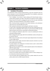
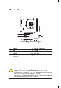


Hardware Installation
- 18 -
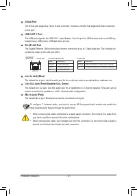
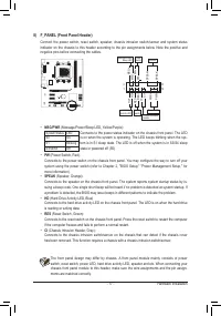
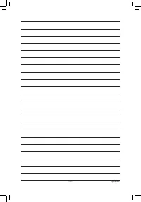
9) F_AUDIO (Front Panel Audio Header)
The front panel audio header supports Intel High Definition audio (HD) and AC'97 audio. You may connect
your chassis front panel audio module to this header. Make sure the wire assignments of the module con-
nector match the pin assignments of the motherboard header. Incorrect connection between the module
connector and the motherboard header will make the device unable to work or even damage it.
Pin No. Definition
1
MIC2_L
2
GND
3
MIC2_R
4
-ACZ_DET
5
LINE2_R
6
GND
7
FAUDIO_JD
8
No Pin
9
LINE2_L
10
GND
Pin No. Definition
1
MIC
2
GND
3
MIC Power
4
NC
5
Line Out (R)
6
NC
7
NC
8
No Pin
9
Line Out (L)
10
NC
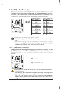
For HD Front Panel Audio:
For AC'97 Front Panel Audio:
•
The front panel audio header supports HD audio by default.
•
Audio signals will be present on both of the front and back panel audio connections simultane-
ously.
•
Some chassis provide a front panel audio module that has separated connectors on each wire
instead of a single plug. For information about connecting the front panel audio module that
has different wire assignments, please contact the chassis manufacturer.
9
1
10
2
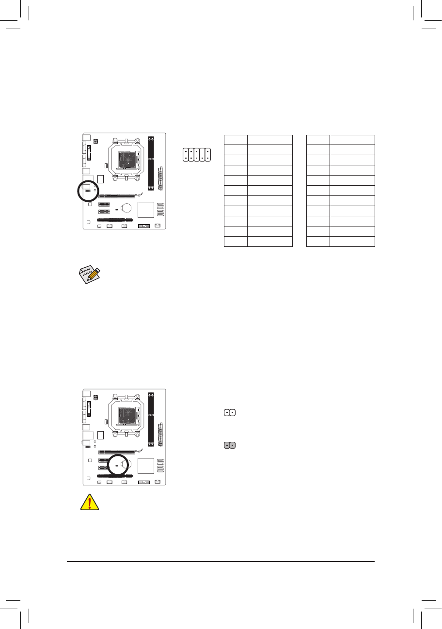
10) CLR_CMOS (Clearing CMOS Jumper)
Use this jumper to clear the CMOS values (e.g. date information and BIOS configurations) and reset
the CMOS values to factory defaults. To clear the CMOS values, place a jumper cap on the two pins to
temporarily short the two pins or use a metal object like a screwdriver to touch the two pins for a few
seconds.
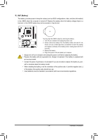
•
Always turn off your computer and unplug the power cord from the power outlet before clear-
ing the CMOS values.
•
After clearing the CMOS values and before turning on your computer, be sure to remove the
jumper cap from the jumper. Failure to do so may cause damage to the motherboard.
•
After system restart, go to BIOS Setup to load factory defaults (select
Load Optimized De-
faults
) or manually configure the BIOS settings (refer to Chapter 2, "BIOS Setup,
" for BIOS
configurations).
Open: Normal
Short: Clear CMOS Values


