Материнские платы GIGABYTE GA M68MT D3P rev 3 - инструкция пользователя по применению, эксплуатации и установке на русском языке. Мы надеемся, она поможет вам решить возникшие у вас вопросы при эксплуатации техники.
Если остались вопросы, задайте их в комментариях после инструкции.
"Загружаем инструкцию", означает, что нужно подождать пока файл загрузится и можно будет его читать онлайн. Некоторые инструкции очень большие и время их появления зависит от вашей скорости интернета.


- 15 -
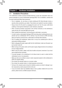
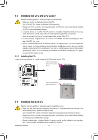
Hardware Installation
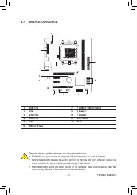
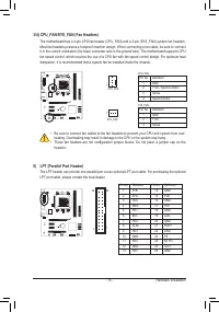
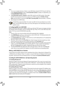
3/4) CPU_FAN/SYS_FAN (Fan Headers)
The motherboard has a 4-pin CPU fan header (CPU_FAN) and a 3-pin (SYS_FAN) system fan headers.
Most fan headers possess a foolproof insertion design. When connecting a fan cable, be sure to connect
it in the correct orientation (the black connector wire is the ground wire). The motherboard supports CPU
fan speed control, which requires the use of a CPU fan with fan speed control design. For optimum heat
dissipation, it is recommended that a system fan be installed inside the chassis.
CPU_FAN:
Pin No. Definition
1
GND
2
+12V / Speed Control
3
Sense
4
Speed Control
CPU_FAN
DEBUG
PORT
G.QBOFM
1
•
Be sure to connect fan cables to the fan headers to prevent your CPU and system from over-
heating. Overheating may result in damage to the CPU or the system may hang.
•
These fan headers are not configuration jumper blocks. Do not place a jumper cap on the
headers.
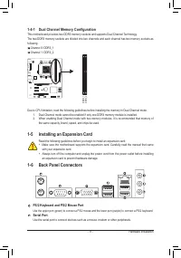
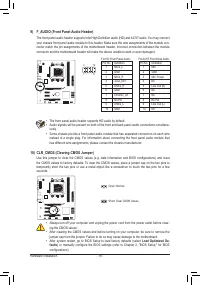
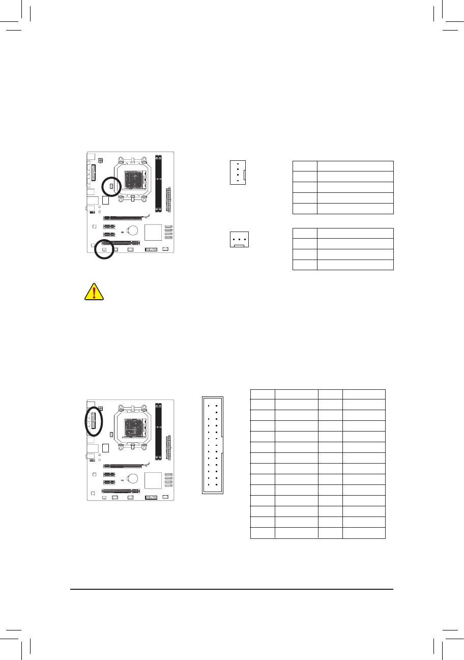
5) LPT (Parallel Port Header)
The LPT header can provide one parallel port via an optional LPT port cable. For purchasing the optional
LPT port cable, please contact the local dealer.
SYS_FAN
SYS_FAN:
Pin No. Definition
1
GND
2
+12V
3
Sense
1
Pin No. Definition
14
GND
15
PD6
16
GND
17
PD7
18
GND
19
ACK-
20
GND
21
BUSY
22
GND
23
PE
24
No Pin
25
SLCT
26
GND
Pin No. Definition
1
STB-
2
AFD-
3
PD0
4
ERR-
5
PD1
6
INIT-
7
PD2
8
SLIN-
9
PD3
10
GND
11
PD4
12
GND
13
PD5
DEBUG
PO
RT
G.QBOFM
26
25
1
2


