Материнские платы GIGABYTE G1 Assassin rev 1 0 - инструкция пользователя по применению, эксплуатации и установке на русском языке. Мы надеемся, она поможет вам решить возникшие у вас вопросы при эксплуатации техники.
Если остались вопросы, задайте их в комментариях после инструкции.
"Загружаем инструкцию", означает, что нужно подождать пока файл загрузится и можно будет его читать онлайн. Некоторые инструкции очень большие и время их появления зависит от вашей скорости интернета.


- 29 -
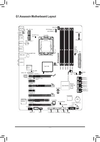
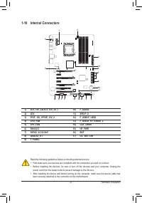
Hardware Installation
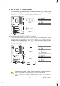
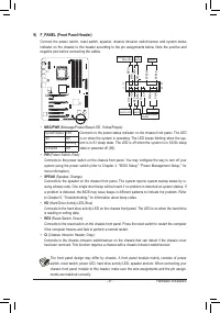
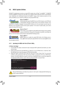
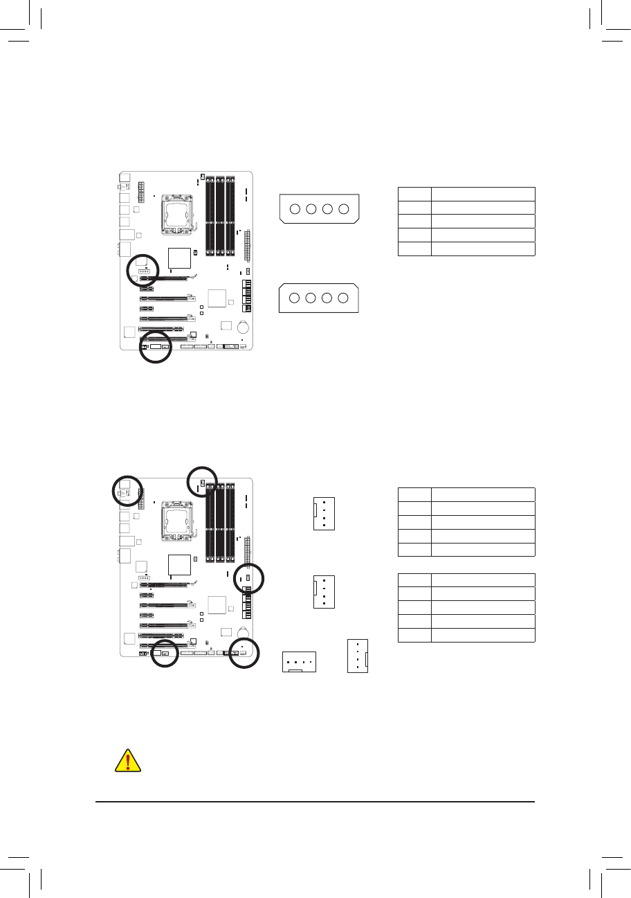
4/5/6) CPU_FAN/SYS_FAN/FAN1/FAN2/FAN3 (Fan Headers)
All fan headers on this motherboard are 4-pin and support fan speed control function. Most fan headers
possess a foolproof insertion design. When connecting a fan cable, be sure to connect it in the correct
orientation (the black connector wire is the ground wire). The speed control function requires the use of
a fan with fan speed control design. For optimum heat dissipation, it is recommended that a system fan
be installed inside the chassis.
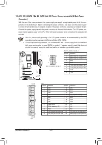
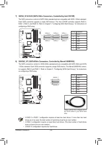
3) PCIE_12V_1/PCIE_12V_2 (Power Connectors)
The power connectors provide auxiliary power to the onboard PCI Express x16 slots. When two or more
graphics cards are installed, we recommend that you connect the power cables from the power supply to
the PCIE_12V_1 and PCIE_12V_2 connectors, or system instability may occur.
PCIE_12V_1
1
CPU_FAN
DEBUG
PORT
G.QBOFM
1
FAN1/FAN2
•
Be sure to connect fan cables to the fan headers to prevent your CPU and system from over-
heating. Overheating may result in damage to the CPU or the system may hang.
•
These fan headers are not configuration jumper blocks. Do not place a jumper cap on the
headers.
PCIE_12V_2
1
FAN3
DEBUG
PORT
G.QBOFM
1
DEBUG
PORT
G.QBOFM
1
CPU_FAN:
SYS_FAN/FAN1/FAN2/FAN3:
Pin No.
Definition
1
GND
2
+12V
3
Sense
4
Speed Control
Pin No.
Definition
1
GND
2
+12V / Speed Control
3
Sense
4
Reserve
Pin No.
Definition
1
VCC
2
GND
3
GND
4
+12V
SYS_FAN
DEBUG
PORT
G.QBOFM
1


