Лобзики Graphite 58G061 - инструкция пользователя по применению, эксплуатации и установке на русском языке. Мы надеемся, она поможет вам решить возникшие у вас вопросы при эксплуатации техники.
Если остались вопросы, задайте их в комментариях после инструкции.
"Загружаем инструкцию", означает, что нужно подождать пока файл загрузится и можно будет его читать онлайн. Некоторые инструкции очень большие и время их появления зависит от вашей скорости интернета.


12
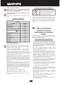
Range of use covers repair and building works, and any work from
the range of individual, amateur activities (tinkering).
Use the power tool according to the manufacturer’s instructions
only.
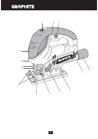
DESCRIPTION OF DRAWING PAGES
Below enumeration refers to the device elements depicted on the
drawing pages of this manual.
1.
Switch
2.
Switch lock button
3.
Adaptor
4.
Dust extraction outlet
5.
Footplate
6.
Guiding roller
7.
Blade holder
8.
Guard
9.
Work speed control wheel
10.
Switch for pendulum action setting
11.
Blade protection
12.
Edge guide locking screws
13.
Laser switch
14.
Laser beam aperture
* Differences may appear between the product and drawing.
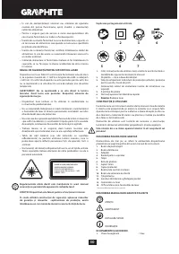
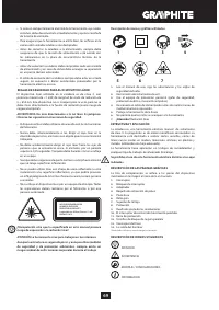
MEANING OF SYMBOLS
CAUTION
WARNING
ASSEMBLY / SETTINGS
INFORMATION
EQUIPMENT AND ACCESSORIES
1.
Hexagonal key
- 1 pce
2.
Dust extraction adaptor
- 1 pce
3.
Edge guide
- 1 pce
4.
Transport case
- 1 pce
PREPARATION FOR OPERATION
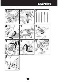
BLADE INSTALLATION
Disconnect the power tool from power supply.
Installation and removal of the blade is toolless.
•
Set the switch for pendulum action (
10
) to position “
III
” and lift
the guard (
8
) (
fig. A
).
•
Pull lever of the blade holder (
7
) and slide blade into the blade
holder (
7
) to mechanical stop (blade teeth should be faced
forward) (
fig. B
).
•
Important! Make sure the blade is properly positioned in the
guiding roller (
6
).
•
Release the lever of the blade holder (
7
) and ensure the blade is
properly fixed.
•
Blade removal is similar to installation, only the sequence of
actions is reversed.
Use blades suitable for T-shank holder mechanism, as shown on
fig. C.
DUST EXTRACTION
To improve dust extraction from processed material surface, the
jigsaw is equipped with own dust blow-off and extraction system,
which cleans the surface being cut. Dust blow-off and extraction
system is more efficient when the guard is lowered.
•
Slide adaptor (
3
) into the dust extraction stub (
4
) and turn
counter-clockwise to secure (
fig. D
).
•
Attach suction hose of the dust extraction system to the adaptor
(
3
). Make sure the connection is tight.
BLADE STORAGE
Jigsaw features convenient clip for blade storage in the rear part of
the footplate (
5
).
OPERATION / SETTINGS
SWITCHING ON / SWITCHING OFF
Before connecting the jigsaw to a power supply always check that
power supply voltage matches rated voltage on the label fixed on
the power tool.
Switching on
– press the switch button (
1
) and hold in this position.
Switching off
– release pressure on the switch (
1
).
Locking the switch (continuous operation)
Switching on:
•
Press the switch button (
1
) and hold in this position.
•
Press the switch lock button (
2
) (
fig. E
).
•
Release pressure on the switch button (
1
).
Switching off:
•
Press and release the switch button (
1
).
CONTROL OF JIGSAW OPERATION SPEED
You can control rotational speed of jigsaw motor by turning and
setting the work speed control wheel (
9
) in desired position. It allows
to adjust the power tool working speed to match characteristics of
processed material. Speed control range is 1 to 6.
The bigger the number on the wheel rim (9) (fig. F), the greater the
jigsaw operation speed.
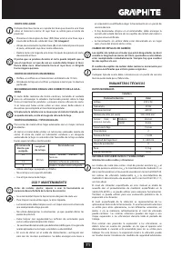
BLADE PENDULUM ACTION CONTROL
Besides reciprocating movement control there is also possibility
to set blade pendulum action level. It allows for better adjustment
of the tool operation parameters to type of processed material.
Pendulum action is controlled in steps with the switch for pendulum
action setting (
10
) and its range is
0
to
III
(
fig. G
). The table below
gives the best choices of pendulum action setting for various
materials:
Sheet metal plate, generally: 0
Steel sheet: 0 – I
Sheet aluminium: I – II
Plastics: I – II
Plywood: 0 – I
Wood: I - III
Set the switch for pendulum action to 0 when using knife blade.
Lubrication is recommended for metal cutting.
FOOTPLATE ADJUSTMENT FOR BEVEL CUTTING
Disconnect the power tool from power supply.
Adjustable jigsaw footplate allows to make a bevel cut in the range
from 0
0
to 45
0
(to either side).
•
Use the hexagonal key and loosen the footplate (
5
) fixing screws.
•
Move the footplate (
5
) backwards and tilt right or left (up to 45
0
).
•
Set the footplate (
5
) at desired angle, move forward and tighten
fixing screws to secure it (
fig. H
).
Scale allows for setting the footplate to angles: 0°, 15°, 30° or 45°
(right or left). Always put the hexagonal key in its storage place after
adjustment has been made.
INSTALLATION OF EDGE GUIDE
Disconnect the power tool from power supply.
Guide for parallel cutting may be installed on left or right side of the
jigsaw footplate.
Характеристики

Остались вопросы?Не нашли свой ответ в руководстве или возникли другие проблемы? Задайте свой вопрос в форме ниже с подробным описанием вашей ситуации, чтобы другие люди и специалисты смогли дать на него ответ. Если вы знаете как решить проблему другого человека, пожалуйста, подскажите ему :)


