Лобзики Bosch GST 10,8 V-Li - инструкция пользователя по применению, эксплуатации и установке на русском языке. Мы надеемся, она поможет вам решить возникшие у вас вопросы при эксплуатации техники.
Если остались вопросы, задайте их в комментариях после инструкции.
"Загружаем инструкцию", означает, что нужно подождать пока файл загрузится и можно будет его читать онлайн. Некоторые инструкции очень большие и время их появления зависит от вашей скорости интернета.


16
| English
1 619 P11 351 | (1.10.13)
Bosch Power Tools
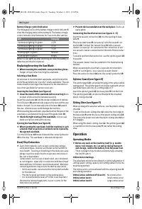
Battery Charge-control Indication
The three green LEDs of the battery charge-control indicator
5
show the charging status of the battery
1
. The battery charge-
control indicator only illuminates for 5 seconds after start-up.
When no LED lights up after switching on, then the battery is
defective and must be replaced.
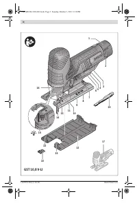
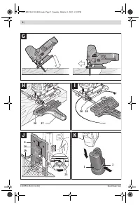
Replacing/Inserting the Saw Blade
When mounting the saw blade, wear protective gloves.
Danger of injury when touching the saw blade.
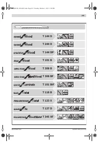
Selecting a Saw Blade
An overview of recommended saw blades can be found at the
end of these instructions. Use only T-shank saw blades. The saw
blade should not be longer than required for the intended cut.
Use a thin saw blade for narrow curve cuts.
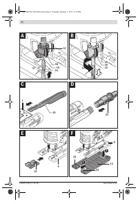
Inserting the Saw Blade (see figure A)
Clean the shank of the saw blade before inserting it.
An
unclean shank cannot be fastened securely.
Insert the saw blade
14
into the stroke rod
11
until it latches.
The SDS lever
18
automatically snaps to the rear and the saw
blade is locked. Do not manually press the lever
18
toward
the rear, otherwise you could damage the machine.
While inserting the saw blade, pay attention that the back of the
saw blade is positioned in the groove of the guide roller
10
.
Check the tight seating of the saw blade.
A loose saw
blade can fall out and lead to injuries.
Ejecting the Saw Blade (see figure B)
When ejecting the saw blade, hold the machine in such
a manner that no persons or animals can be injured by
the ejected saw blade.
Turn the SDS lever
18
forward towards the contact protector
19
to the stop. The saw blade is released and ejected.
Dust/Chip Extraction
Dusts from materials such as lead-containing coatings,
some wood types, minerals and metal can be harmful to
one’s health. Touching or breathing-in the dusts can cause
allergic reactions and/or lead to respiratory infections of
the user or bystanders.
Certain dusts, such as oak or beech dust, are considered
as carcinogenic, especially in connection with wood-treat-
ment additives (chromate, wood preservative). Materials
containing asbestos may only be worked by specialists.
– As far as possible, use a dust extraction system suitable
for the material.
– Provide for good ventilation of the working place.
– It is recommended to wear a P2 filter-class respirator.
Observe the relevant regulations in your country for the
materials to be worked.
Prevent dust accumulation at the workplace.
Dusts can
easily ignite.
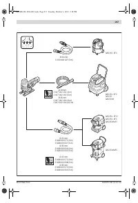
Connecting the Dust Extraction (see figures C – E)
Insert the vacuum connection
20
into the opening of base
plate
9
.
Place a vacuum hose
21
(accessory) onto the vacuum con-
nection
20
. Connect the vacuum hose
21
with a vacuum
cleaner (accessory). An overview for the connection of vari-
ous vacuum cleaners can be found at the end of these instruc-
tions.
To enable optimum dust extraction, use the splinter guard
22
if possible.
The vacuum cleaner must be suitable for the material being
worked.
When vacuuming dry dust that is especially detrimental to
health or carcinogenic, use a special vacuum cleaner.
Place the extraction hood
16
onto the contact protector
19
.
Splinter Guard (see figure E)
The splinter guard
22
can prevent fraying of the surface while
sawing wood. The splinter guard can only be used with certain
saw blade types and only at a cutting angle of 0 ° .
Insert the splinter guard
22
into base plate
9
from the front.
The splinter guard
22
can also be fitted with the mounted
plastic sliding shoe
12
.
Sliding Shoe (see figure F)
When working with sensitive surfaces, use the plastic sliding
shoe
12
.
To put on the plastic sliding shoe
12
, place the front edge of
the base plate
9
under the nose of the plastic sliding shoe
23
.
Then press the power tool onto the plastic sliding shoe
12
un-
til it engages.
When using the plastic sliding shoe
12
, the splinter guard
22
is inserted not into the base plate
9
, but rather the sliding
shoe.
Operation
Operating Modes
Before any work on the machine itself (e. g. mainte-
nance, tool change, etc.) as well as during transport
and storage, remove the battery from the power tool.
There is danger of injury when unintentionally actuating
the On/Off switch.
Orbital Action Settings
The adjustable orbital action allows for optimal adaptation of
cutting speed, cutting capacity and cutting pattern to the ma-
terial being worked.
The orbital action can be adjusted with the adjusting lever
8
,
even during operation.
LED
Capacity
Continuous lighting 3 x green
2/3
Continuous lighting 2 x green
1/3
Continuous lighting 1 x green
< 1/3
Flashing light 1 x green
Reserve
Flashing light 3 x green
Empty
Orbital action switched off (level 0):
No orbital action
Orbital action level I:
Small orbital action
Orbital action level II:
Large orbital action
OBJ_BUCH-1994-001.book Page 16 Tuesday, October 1, 2013 2:18 PM
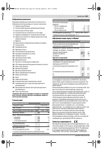
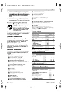
Содержание
- 120 Указания по технике безопасности для
- 121 Описание продукта и услуг; Применение по назначению
- 122 Технические данные; Сборка; Зарядка аккумулятора
- 123 Установка/смена пильного полотна
- 124 Работа с инструментом; Режимы работы
- 125 Указания по применению; Техобслуживание и сервис; Техобслуживание и очистка
- 126 Транспортировка; Українська; Вказівки з техніки безпеки; Загальні застереження для електроприладів
- 218 Сайт техники и электроники; Наш сайт
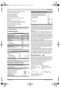
Характеристики

Остались вопросы?Не нашли свой ответ в руководстве или возникли другие проблемы? Задайте свой вопрос в форме ниже с подробным описанием вашей ситуации, чтобы другие люди и специалисты смогли дать на него ответ. Если вы знаете как решить проблему другого человека, пожалуйста, подскажите ему :)


