
Газонокосилки STIGA Combi 55 SVQ H 294557838/ST2 - инструкция пользователя по применению, эксплуатации и установке на русском языке. Мы надеемся, она поможет вам решить возникшие у вас вопросы при эксплуатации техники.
Если остались вопросы, задайте их в комментариях после инструкции.
"Загружаем инструкцию", означает, что нужно подождать пока файл загрузится и можно будет его читать онлайн. Некоторые инструкции очень большие и время их появления зависит от вашей скорости интернета.


4
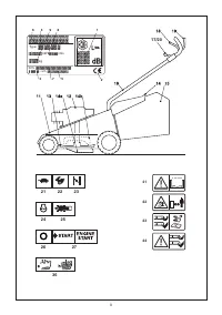
the cutting means housing. Disconnect the spark plug
cap and read the instructions before carrying out any
maintenance or repairs.
44.
Danger of cutting yourself. Cutting means. Do not put
hands or feet near or under the opening of the cutting
means housing.
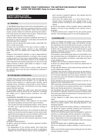
OPERATING INSTRUCTIONS
For information on the engine and the battery (if sup
-
plied), read the relevant owner manuals.
NOTE – The number which precedes each paragraph
links the references in the text to the respective illus
-
trations (listed on page iii and following pages).
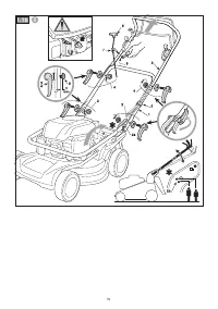
1. COMPLETE ASSEMBLY
NOTE
The machine can be supplied with some parts al-
ready assembled.
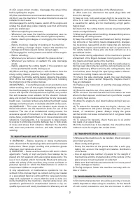
WARNING!
Unpacking and completing the assem-
bly should be done on a flat and stable surface, with
enough space for moving the machine and its packag-
ing, always making use of suitable equipment.
Disposal of the packaging should be done in accord-
ance with the local regulations in force.
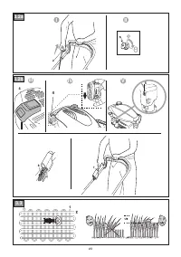
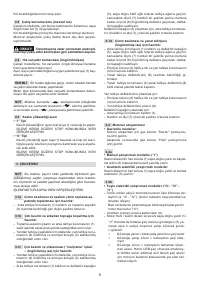
1.1a
Assembling the handle (Type“I”)
Return the lower part of the handle (1) to the work posi
-
tion and fasten it to the side chassis supports as shown
in the diagram, using the knobs (2) and relative nuts and
bolts supplied.
The handle (1) can be height-adjusted in two different po
-
sitions by inserting the pins (2a) in one of the two square
seats (2b) on the supports.
Assemble the top part (3) and fasten in place using the
knobs (4) and relative screws supplied.
Secure the control cables using the cable fastener (5).
• Manual ignition models
• Electric key ignition models
Insert the starter cable (6) in the spiral (7) and tighten
the nut (8).
1.1b
Assembling the handle (Type“II”)
Return the lower part of the handle (1) to the work position
and fasten it to the side chassis supports as shown in the
diagram, using the handles (2) and relative nuts and bolts.
Make sure the pins (2a) are inserted in one of the two holes
(2b) on the side supports of the chassis so as to achieve the
correct height of the handle.
Assemble the top part (3) and fasten in place using the le
-
vers (4) and relative screws previously removed from their
respective holes.
The rings (9) on the levers (2) and (4) must be screwed on
so that the distance from the handle is around 9 mm (when
the levers are released) to ensure secure fastening without
requiring too much effort to tighten or release the levers.
Secure the control cables using the cable fastener (5).
• Manual ignition models
• Electric key ignition models
Insert the starter cable (6) in the spiral (7) and tighten
the nut (8).
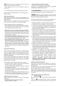
1.1c
Assembling the handle (Type“III”)
Return the handle (1) to the work position and fasten it to the
side chassis supports as shown in the diagram, using the
handles (2) and relative nuts and bolts.
Make sure the pins (2a) are inserted in one of the two holes
(2b) on the side supports of the chassis so as to achieve the
correct height of the handle.
The rings (9) on the levers (2) must be screwed on so that
the distance from the handle is around 9 mm (when the le
-
vers are released) to ensure secure fastening without re
-
quiring too much effort to tighten or release the levers.
• Manual ignition models
• Electric key ignition models
Insert the starter cable (6) in the spiral (7) and tighten
the nut (8).
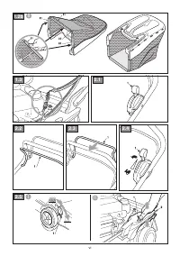
1.2a
Assembling the grass catcher (Type“I”)
Insert the frame (11) in the grass catcher (12) and snap on
all the plastic sections (13), using a screwdriver as illustrat
-
ed.
1.2b
Assembling the grass catcher (Type“II”)
With the grass catcher turned upside down, snap on all the
plastic sections (21) to the chassis (22), using a screwdriv
-
er as illustrated.
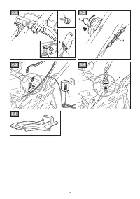
1.3
Battery connection
• Electric key ignition models
Connect the battery cable to the general wiring connec
-
tor on the lawnmower.
• Electric push-button ignition models
Insert the supplied battery in the relative engine com
-
partment (par. 3.2b, “III - “IV”).
Some models have an engine with non-removable built-
in battery (par. 3.2b, “V).
Follow the instructions in the engine manual for further
details on the engine.
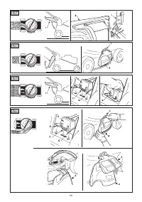
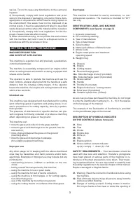
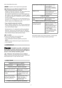
2. CONTROLS DESCRIPTION
NOTE
The meanings of the symbols on controls are ex
-
plained in the previous pages.
2.1
Throttle lever (if fitted)
The throttle adjusts the engine rpm and the speed of the
cutting means.
The throttle is controlled by the lever (1).
Lever positions are indicated on the relevant plate.
Some models have a fixed speed engine with no need for
a throttle.
2.2
Engine brake lever / cutting means
The cutting means brake is controlled by the lever (1) which
must be held against the handle during ignition and during
lawnmower operations.
The engine stops when the lever is released.
2.3
Drive lever (where applicable)
On power-driven models, push the lever (1) toward the han
-
dle for forward movement.
The lawnmower stops moving forward when the lever is
released.
The engine must always be ignited with the drive disen
-
gaged.


