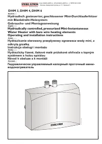
Водонагреватели Stiebel Eltron DHM 4 - инструкция пользователя по применению, эксплуатации и установке на русском языке. Мы надеемся, она поможет вам решить возникшие у вас вопросы при эксплуатации техники.
Если остались вопросы, задайте их в комментариях после инструкции.
"Загружаем инструкцию", означает, что нужно подождать пока файл загрузится и можно будет его читать онлайн. Некоторые инструкции очень большие и время их появления зависит от вашей скорости интернета.

9
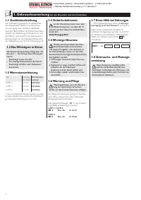
2.5 Regulations and provisi-
ons
•
Installation (water and electrical installation),
as well as the first star t-up and maintenance
of this unit, may only be carried out by a
qualified installer in accordance with these
instructions.
•
Faultless operation and operational safety
are only guaranteed if the original acces-
sories and spare par ts intended for the unit
are used.
The following should also be observed:
•
In accordance with IEE and WRC Regula-
tions.
•
Regulations of the local energy supply com-
pany.
•
Regulations of the relevant water supply
company.
•
The unit rating plate.
•
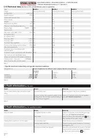
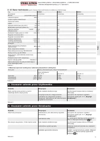
Technical data (see Table 1).
The specific electrical resistance of
the water must not be lower than
specified on the rating plate. In the case it is
used out of the water grid supply network,
the lowest electrical resistance of the water
is to be taken into account (see Table 2).
Your water supply company will advise you
of the specific electrical resistance or the
electrical conductivity of the water.
Water installation:
•
A safety valve is not necessar y.
•
Operating the unit with preheated water
only up to max. 25 °C is permitted!
•
Fittings for pressurised units are not permit-
ted!
Electrical installation:
•
It must be possible to isolate the unit from
the main supply on all poles with an isolat-
ing distance of at least 3 mm, for example
using fuses.
2.6 Installation location
Under-sink installation B
The appliance should be installed
according to choice as an under-sink
unit‘ in a closed, frost free room in the
vincinity of a water draw off point.
Dismantled unit is to be stored in a frost-
free place, as residual water always remains
in the unit.
2.7 Unit installation
C
1
Loosen cover securing screws by two
turns.
2
Using a screwdriver, release the snap
closing catch.
3
Take off the unit front cover with heating
block.
4
Fix the unit rear panel to the wall using
dowels and screws; use the unit rear
panel as a drilling template.
5
Hook on the unit front panel with heating
block.
6
Engage the heating block in the snap
closing catch.
7
Secure the unit front cover with 2 screws.
2.8 Tap installation
•
screw T-piece on angle valve
•
screw cold water connection on to T-piece
•
screw connection hose (
13
) on to the
T-piece
•
screw the free end of connection hose (
13
)
on to the cold water inlet of the DHM,
while doing this, you must hold the con-
nection piece of the unit in position with a
14 mm spanner to avoid any damage
•
screw the warm-water-pipe of the tap-
fitting on to the units warm water outlet
fitting, while doing this, you must hold the
connection piece of the unit in position
with a 14 mm spanner.
2.9 Electrical connection
D
The unit must be connected to the
protective earth terminal.
This appliance is fitted with a power supply
cable.
The units are fitted with an electric cable for a
fixed electrical installation
D
.
The elctrical fixed connection may be perfor-
med with a diamater for the wire of 3 times
6 mm².
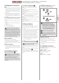
2.10 First start-up
(may only be
carried out by a qualified installer)
26_02_02_0656
1
2
1 Fill and deaerate the unit.
Note: danger of running dry!
Open and close the tap repeatedly
until the pipework and the unit are
free of air. For guidance on air, see
„
2.2 Important information
“.
2 Switch on the mains power.
3 Test the operating mode of the
instantaneous water heater and
armature.
Handover of the unit
Explain the function of the unit to the user
and familiarize him or her with its use.
•
Draw the user’s attention to possible ha-
zards (scalding).
•
Hand over these instructions for careful
retention.
2.11 Special accessories
Jet regulator
„
SR
“ for use in the jet-regulator
screw fitting M22/M24.
DHM 3 / DHM 4:
SR 3
order no: 14 35 02
with output regulator.
DHM 6:
SR 5
order no. 27 05 82
English
www.stiebel-gmbh.ru • info@stiebel-gmbh.ru • +7 (495) 565-34-82
г. Москва, Каширский проезд, д. 17, строение 5
Содержание
- 2 Gebrauchsanweisung; Русский; Окружающая среда и; English; Safety instruction
- 3 braun
- 17 неисправностей пользователем; Инструкция по монтажу; для квалифицированного специалиста; по безопасности; Инструкция по эксплуатации; для пользователя и специалиста
- 18 Специальная арматура; Предписания и нормы; Важные указания
- 19 Устранение неисправностей; Технические характеристики; электропроводности воды
- 21 Утилизация устаревших приборов; Recycling; Recycling of obselete appliances


