
Триммеры Makita BC231UDZ - инструкция пользователя по применению, эксплуатации и установке на русском языке. Мы надеемся, она поможет вам решить возникшие у вас вопросы при эксплуатации техники.
Если остались вопросы, задайте их в комментариях после инструкции.
"Загружаем инструкцию", означает, что нужно подождать пока файл загрузится и можно будет его читать онлайн. Некоторые инструкции очень большие и время их появления зависит от вашей скорости интернета.


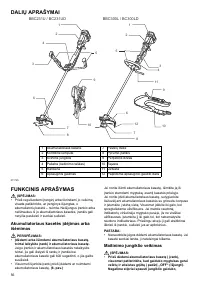


14
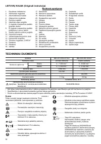
011713
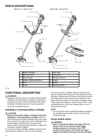
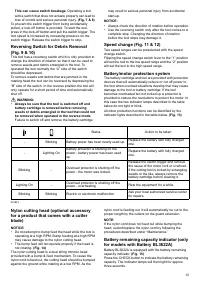
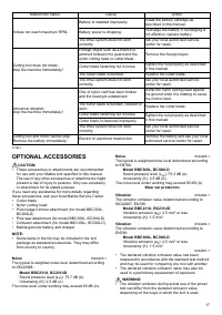
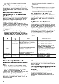
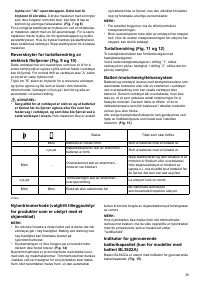
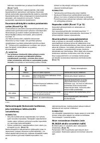
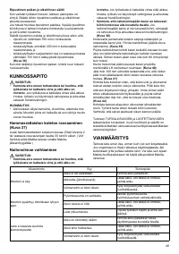
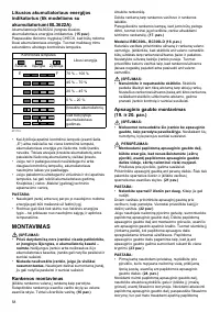
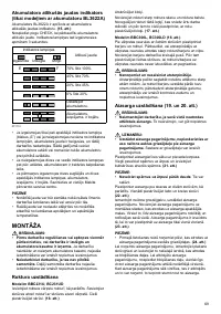
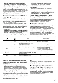
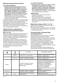
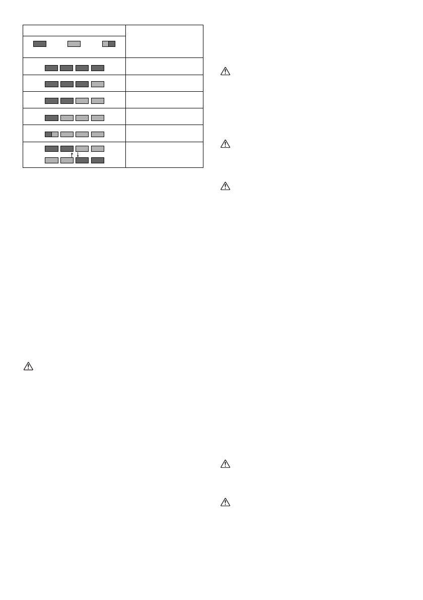
• When only the lowermost indicator lamp (next to the
“E”) blinks, or when none of the indicator lamps light,
the battery capacity has run out, so the tool does not
operate. In these cases, charge the battery or replace
the empty battery with a fully charged one.
• When two or more indicator lamps do not light even
after charging is complete, the battery has reached the
end of its service life.
• When the upper two and lower two indicator lamps light
alternately, the battery may have malfunctioned.
Contact your local Makita authorized service center.
NOTE:
• The indicated capacity may be lower than the actual
level during use or immediately after using the tool.
• Depending on the conditions of use and the ambient
temperature, the indication may differ slightly from the
actual capacity.
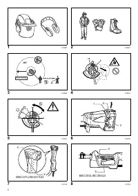
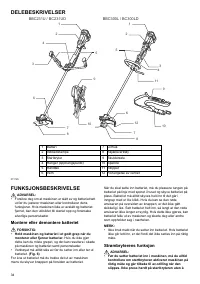
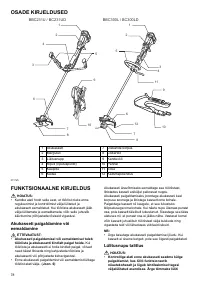
ASSEMBLY
WARNING:
•
Always be sure that the tool is switched off and
battery cartridge is removed before carrying out
any work on the tool.
Failure to switch off and remove
the battery cartridge may result in serious personal
injury from accidental start-up.
•
Never start the tool unless it is completely
assembled.
Operation of the tool in a partially
assembled state may result in serious personal injury
from accidental start-up.
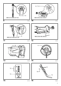
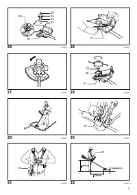
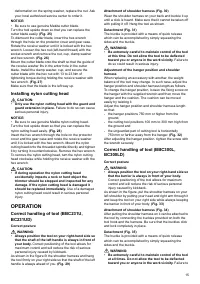
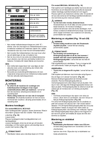
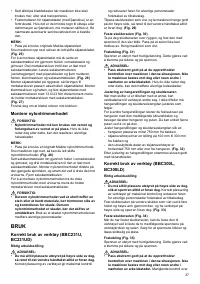
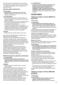
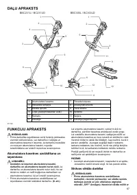
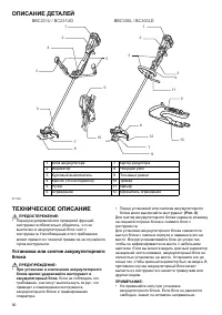
Installing the handle
For model BBC231U, BC231UD
Insert the shaft of the handle into the grip as shown. Align
the screw hole in the grip with the one in the shaft. Tighten
the screw securely.
(Fig. 16)
Loosen knob.
Place handle between handle clamp and handle holder.
Adjust the handle to an angle that provides a comfortable
working position and then secure by firmly hand-
tightening knob.
(Fig. 17)
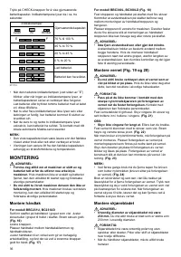
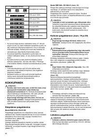
For model BBC300L, BC300LD (Fig. 18)
Fit the barrier and grip onto the shaft pipe with four
screws. Make sure that the spacer on the shaft pipe is
located between the grip/barrier assembly and the
hanger.
Position the barrier on the left side of the tool. Then
tighten four screws so that the grip/barrier assembly
cannot move or rotate on the shaft pipe.
WARNING:
•
Do not remove or shrink the spacer.
The spacer
keeps a certain distance between both hands. Setting
the grip/barrier assembly close to the other grip beyond
the length of the spacer may cause loss of control and
serious personal injury.
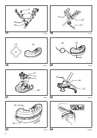
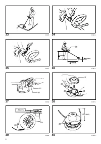
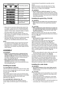
Installing the guard (Fig. 19 & 20)
WARNING:
•
Never use the tool without the guard illustrated in
place.
Failure to do so can cause serious personal
injury.
CAUTION:
•
While installing the guard extension be careful not
to contact the sharp nylon cord cutter provided on
the guard extension.
Contact with the cutter could
result in personal injury.
Attach the protector cover onto the gear case. Slightly
push the wings outward and put the bolts into the holes in
the wings.
(Fig. 21)
NOTICE:
•
Do not push the wings outward too much.
Otherwise it may break.
Fix the guard to the clamp with two bolts as shown.
Tighten the right and left bolts evenly.
(Fig. 22)
When using a nylon cutting head, mount the guard
extension. Place the guard extension onto the mounting
track provided on the lower edge of the guard. And slide it
into position until the guard extension clicks and locks into
place. The guard extension is designed so that it will only
mount onto the guard in one direction.
(Fig. 23)
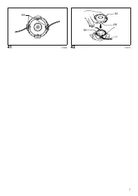
NOTE:
• Remove tape adhered to cutter, which cuts nylon cord,
on guard extension at the first use.
(Fig. 24)
To remove the guard extension, use a flat-blade
screwdriver and place it into the small notch provided on
the locking nub. To unlock the guard extension press
down on the locking nub while sliding the lower guard
extension in the direction indicated in the figure. Once the
guard extension starts to slide it is unlocked and can be
removed by continuing to slide it off of the guard.
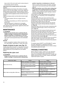
Installing the cutter blade
WARNING:
•
The outside diameter of the cutter blade must be
230 mm.
Never use any blade exceeding 230 mm in
outside diameter.
CAUTION:
• The cutter blade must be well polished, free of cracks
or breakage. Polish or replace the cutter blade every
three hours of operation.
• Always wear gloves when handling the cutter blade.
• Always attach the blade cover when the tool is not in
use or is being transported.
• The cutter blade-fastening nut (with spring washer) is a
consumable part. If there appears any wear or
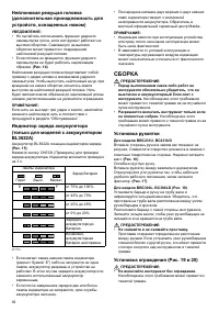
Indicator lamps
Remaining capacity
Lighted
Off
Blinking
E
F
70% to 100%
45% to 70%
20% to 45%
0% to 20%
Charge the battery.
The battery may have
malfunctioned.


