
Шуруповерты Verto 10.8В 50G272 - инструкция пользователя по применению, эксплуатации и установке на русском языке. Мы надеемся, она поможет вам решить возникшие у вас вопросы при эксплуатации техники.
Если остались вопросы, задайте их в комментариях после инструкции.
"Загружаем инструкцию", означает, что нужно подождать пока файл загрузится и можно будет его читать онлайн. Некоторые инструкции очень большие и время их появления зависит от вашей скорости интернета.


13
Safe position of the direction selector switch (
4
) is in the middle, it
prevents accidental star ting of the power tool.
•
D
rill cannot be star ted, when the switch is in this position.
•
Use this position of the switch to change drills or bits.
•
Before star ting the tool make sure the position of the direction
selector switch (
4
) is correct.
Do not change direction of rotation when the drill spindle is
rotating.
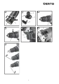
C H A N G E O F G E A R
G
ear switch (
3
) (
fig. F
) allows to increase the range of rotational
speed.
Gear I
: small speed range, big torque
Gear II
: wider speed range, small torque.
Set the gear switch in position appropriate for the works to per form.
When the switch is blocked and cannot move, turn the spindle
slightly.
Never change the gear switch position when drill is operating. It
may damage the power tool.
Long lasting drilling at low rotational speed of the spindle
may cause motor overheating. Provide regular breaks during
operation or let the tool operate at maximum speed with no load
for approximately 3 minutes.
OPERATION AND MAINTENANCE
M A I N T E N A N C E A N D S TO R AG E
•
C
leaning the device after each use is recommended.
•
D
o not use water or any other liquid for cleaning.
•
C
lean the drill with a dr y cloth or blow with compressed air at low
pressure.
•
D
o not use any cleaning agents or solvents, they may damage
plastic par ts.
•
C
lean ventilation holes in the motor casing regularly to prevent
device overheating.
•
In case of excessive commutator sparking, have the technical
condition of carbon brushes of the motor checked by a qualified
person.
•
Store the drill in a dr y place, beyond reach of children.
Q U I C K R E L E A S E C H U C K R E P L AC E M E N T
Quick-release chuck is screwed onto spindle of the drill and
additionally secured with a screw.
•
Set the direction selector switch (
4
) in the middle position.
•
Open jaws of quick release chuck (
1
) and unscrew the fixing screw
(left-hand thread) (
fig. G
).
•
Install hexagonal key in the quick release chuck and tap the other
end of the key.
•
Unscrew the quick release chuck.
•
Installation of the quick release chuck is similar to deinstallation,
only the sequence of actions is reversed.
A
ll defects should be repaired by ser vice workshop authorized by
the manufacturer.
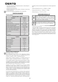
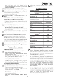
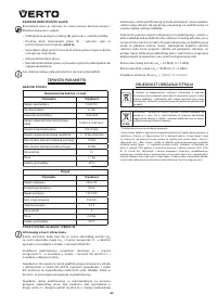
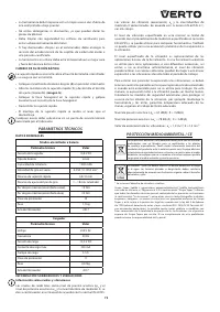
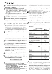
TECHNICAL PARAMETERS
R AT E D PA R A M E T E R S
Cordless drill
Parameter
Value
Battery voltage
10,8 V
DC
Battery type
Li-Ion
Battery capacity
1300 m
A
h
Range of idle rotational speed
0-350 / 0-1350 rpm
Range of quick release chuck
0,8-10 mm
Torque control range
1 – 18 plus drilling
Max. torque (soft drive)
19 Nm
Max. torque (hard drive)
35 Nm
Protection class
III
Weight
1,1 kg
Year of production
2017
Charger
Parameter
Value
Supply voltage
230 V
AC
Power supply frequency
50 Hz
C
harging voltage
13,5 V
DC
Max. charging current
350 m
A
Battery charging time
3-5 h
Protection class
II
Weight
0,07 kg
Year of production
2017
N O I S E L E V E L A N D V I B R AT I O N PA R A M E T E R S
Information regarding noise and vibration
The following levels of emitted noise, such as emitted acoustic
pressure Lp
A
and acoustic power level Lw
A
and measurement
uncer tainty K have been given in the instruction manual as defined
in the
E
N 60745 standard.
The following vibration value (acceleration value) a
h
and
measurement uncer tainty K have been determined as defined in the
E
N 60745-2-1 standard.
The vibration level provided in this instruction manual have been
determined according to the measurement procedure as defined in
the
E
N 60745 standard and can be used for comparison of power
tools. This can be used for preliminar y assessment of exposure to
vibrations.
The provided vibration level is representative for main applications
of the power tool. If the power tool is used for other applications or
with other working tools, and if it is not sufficiently maintained, the
vibration level may var y. The aforementioned reasons may increase
the exposure to vibrations during the entire operating period.
In order to precisely estimate the exposure to vibrations, periods
should be accounted for, in which the power tool is switched off, or
when it is switched on, but not operated. Thus, the total exposure to
vibration may prove considerably lower.
A
dditional safety measures should be taken to protect the user
against effects of vibrations, such as: maintenance of the power tool
and its working tools, ensuring proper temperature of the hands and
proper organisation of work.
Sound pressure level: Lp
A
= 67 dB(
A
); K = 3 dB(
A
)
Sound power level: Lw
A
= 78 dB (
A
) ; K = 3 dB(
A
)
Vibration acceleration: a
h
= 1,9 m/s²; K =1,5 m/s²
ENVIRONMENT PROTECTION / CE
D
o not dispose of electrically powered products with household
wastes, they should be utilized in proper plants. Obtain information on
waste utilization from your seller or local authorities. Used up electric
and electronic equipment contains substances active in natural
environment. Unrecycled equipment constitutes a potential risk for
environment and human health.
Характеристики

Остались вопросы?Не нашли свой ответ в руководстве или возникли другие проблемы? Задайте свой вопрос в форме ниже с подробным описанием вашей ситуации, чтобы другие люди и специалисты смогли дать на него ответ. Если вы знаете как решить проблему другого человека, пожалуйста, подскажите ему :)
