
Шуруповерты Verto 10.8В 50G272 - инструкция пользователя по применению, эксплуатации и установке на русском языке. Мы надеемся, она поможет вам решить возникшие у вас вопросы при эксплуатации техники.
Если остались вопросы, задайте их в комментариях после инструкции.
"Загружаем инструкцию", означает, что нужно подождать пока файл загрузится и можно будет его читать онлайн. Некоторые инструкции очень большие и время их появления зависит от вашей скорости интернета.


12
Use the power tool according to the manufacturer’s instructions
only.
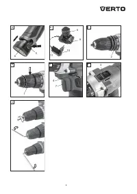
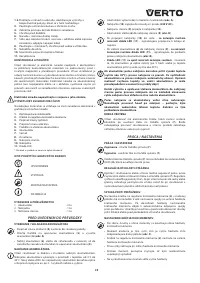
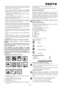
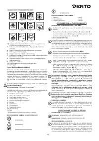
D E S C R I P T I O N O F D R AW I N G PAG E S
Below enumeration refers to the device elements depicted on the
drawing pages of this manual.
1.
Quick-release chuck
2.
Torque adjustment ring
3.
G
ear switch
4.
D
irection selector switch
5.
Batter y lock button
6.
Batter y
7.
Switch
8.
Lighting
9.
C
harging station
10.
C
harger
11.
L
ED
*
D
ifferences may appear between the product and drawing.
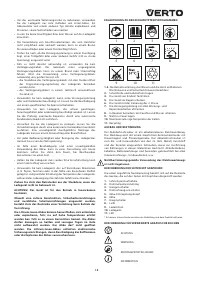
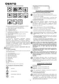
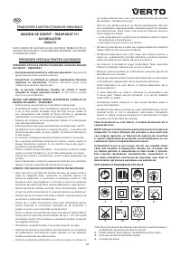
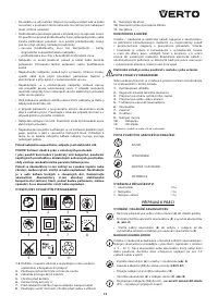
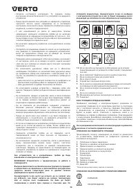
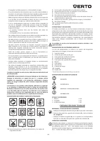
M E A N I N G O F S YM B O L S
CA
UTION
W
A
RNIN
G
A
SS
E
MBLY / S
E
T TIN
G
S
IN
F
ORM
A
TION
E Q U I PM E N T A N D ACC E S S O R I E S
1. Batter y
- 2 pcs
2.
C
harger
- 1 pce
3.
C
harging station
- 1 pce
PREPARATION FOR OPERATION
REMOVING AND INSERTING THE BAT TERY
•
Set the direction selector switch (
4
) in middle position.
•
Push batter y lock buttons (
5
) and slide out the batter y (
6
) (
fig. A
).
•
Inser t charged batter y (
6
) into the handle holder, you should hear
when the batter y lock buttons (
5
) snap.
BAT TERY CHARGING
D
rill is supplied with par tially charged batter y. The batter y should
be charged in ambient temperature between 4
o
C
and 40
o
C
. New
batter y, or one that has not been used for a long time, will reach full
efficiency after approximately 3 to 5 charge/discharge cycles.
•
Remove the batter y (
6
) from the drill (
fig. A
).
•
C
onnect the charger (
10
) to mains socket (
230 V AC
).
•
C
onnect the charging station (
9
) to the charger (
10
).
•
Put the batter y (
6
) inside the charging station (
9
) (
fig. B
).
•
Once the charger (
10
) has been connected to mains
green LED
will light up
(
11
), signalling presence of charging voltage.
•
When the batter y (
6
) is placed in charging station (
9
)
red LED
lights up
(
11
), which indicates that batter y charging is in progress
(
fig. B
).
• Green LED turns on again
(
11
) when the batter y is fully charged
(after 5 hours) or batter y temperature is too high (above 45
0
C
).
When the battery reaches too high temperature during charging
(above 45
0
C) charging is interrupted. Charging resumes
automatically when the battery cools down. This temperature
rise inside the battery is not likely and may never occur.
Each time the battery is removed and inser ted into charging
station during recharge, the charging cycle resets regardless of
the current battery level.
Batteries heat up strongly when charging. Do not operate just
after charging – wait for the battery to cool down to room
temperature. It will prevent battery damage.
S P I N D L E B R A K E
D
rill is equipped with electronic brake, which stops the spindle
immediately after the switch button (
7
) is released. The brake
ensures precision when screwing or drilling and prevents free
spindle rotation after switching off.
OPERATION / SET TINGS
S W I TC H I N G O N / S W I TC H I N G O F F
Switching on
– press the switch button (
7
).
Switching off
– release the switch button (
7
).
E
ach time the switch button (
7
) is pressed, the L
ED
diode (
8
) lights
up to illuminate the workplace.
ROTATIONAL SPEED CONTROL
Increase or reduce pressure on the switch button (
7
) to adjust
drilling or driving speed while operating. Speed adjustment allows
for a soft star t, which prevents dill slipping when drilling holes in
gypsum or glaze, and allows for operation control when screwing
in and out.
OV E R LOA D C LU TC H
PSet the torque adjustment ring (
2
) in appropriate position to
permanently set overload clutch to defined torque value. When the
set torque is reached, overload clutch disconnects automatically. It
prevents screwing screws too deep or damaging the drill.
TO RQUE ADJUSTMENT
•
D
ifferent screws and materials require different torque to be
applied.
•
The bigger the number corresponding to given position, the
bigger is the torque (
fig. C
).
•
Set the torque adjustment ring (
2
) to appropriate torque value.
•
A
lways star t operation with low torque.
•
Increase the torque gradually until obtaining desired results.
•
Use higher settings to unscrew screws.
•
When drilling, choose setting marked with the drill symbol. The
torque is the greatest with this setting.
•
Knowledge how to choose appropriate torque setting comes with
practice
Setting the torque adjustment ring in the drilling position
deactivates the overload clutch.
WO R K I N G TO O L I N S TA L L AT I O N
•
Set the direction selector switch (
4
) in the middle position.
•
Hold the rear ring of the quick release chuck (
1
) and turn the front
ring counter clockwise. Turn until jaws spread properly and allow
to inser t drill or driver bit (
fig. D
).
•
Hold the rear ring of the quick release chuck (
1
), turn front ring
clockwise and tighten firmly to install work tool.
D
einstallation of tool is similar to installation, only the sequence of
actions is reversed.
Make sure the tool position is correct when installing drill or
driver bit in the quick release chuck. Use additional magnetic
adapter as an extension when using shor t driver bits.
LEFT – RIGHT DIREC TION OF ROTATION
C
hoose direction of spindle rotation with the direction selector
switch (
4
) (
fig. E
).
Right rotation
– set the switch (
4
) to the extreme left position.
Left rotation
– set the switch (
4
) to the extreme right position.
* In cer tain cases position of the switch related to rotation may be different than
specified. Please refer to graphic signs placed on the switch or tool body.
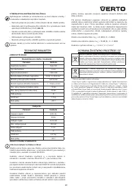
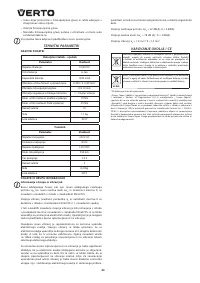
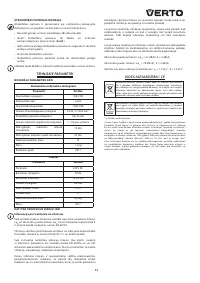
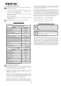
Характеристики

Остались вопросы?Не нашли свой ответ в руководстве или возникли другие проблемы? Задайте свой вопрос в форме ниже с подробным описанием вашей ситуации, чтобы другие люди и специалисты смогли дать на него ответ. Если вы знаете как решить проблему другого человека, пожалуйста, подскажите ему :)
