Шуруповерты Sparky BUR2 12Li-C HD - инструкция пользователя по применению, эксплуатации и установке на русском языке. Мы надеемся, она поможет вам решить возникшие у вас вопросы при эксплуатации техники.
Если остались вопросы, задайте их в комментариях после инструкции.
"Загружаем инструкцию", означает, что нужно подождать пока файл загрузится и можно будет его читать онлайн. Некоторые инструкции очень большие и время их появления зависит от вашей скорости интернета.


8
BR2 12Li-C HD • BUR2 12Li-C HD
EN
Operation
The machine is intended for driving in and loosening
screws as well as for drilling in wood, metal, ceramics
and plastic.
BUR2 12Li-C HD machines are additionally intended for
impact drilling in bricks, brickwork and masonry.
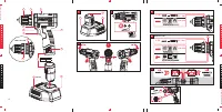
FITTING AND REMOVING THE BATTERY
PACK
To remove the battery from the machine: press the battery
release buttons (4) and take the battery out of the tool.
WARNING:
Always set the forward/reverse
switch (3) in central position before any work on the
machine e. g. fitting and removing a battery, changing
the bit,, transport, maintenance and storage.
To install the battery: Insert the charged battery into the
opening at the base of the power tool until the battery is
securely latched with a click.
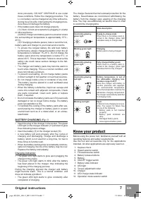
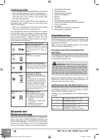
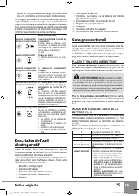
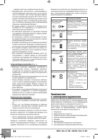
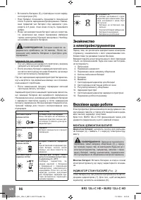
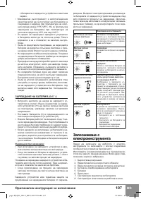
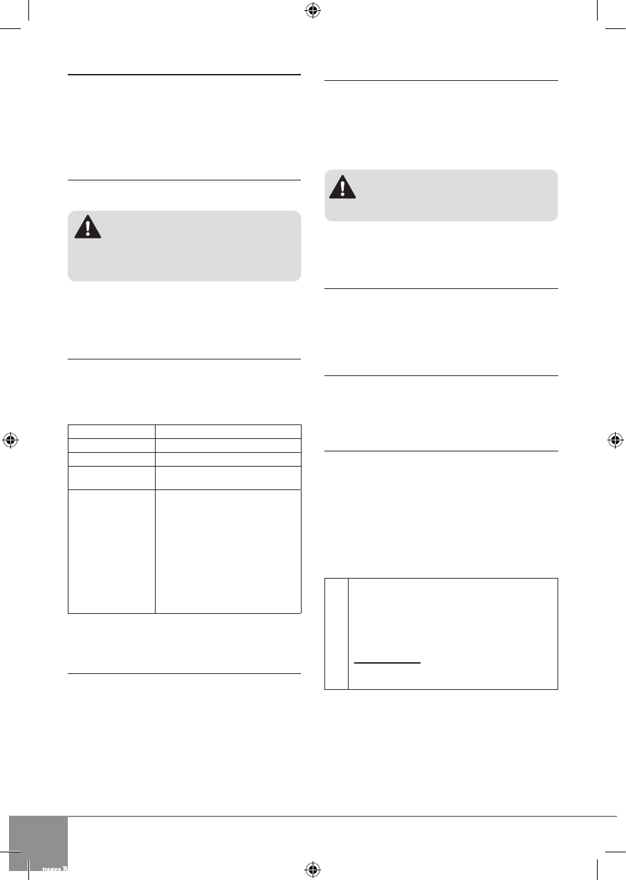
BATTERY STATE INDICATION
(Fig. 2)
The battery state during operation can be checked on
the LED display (7) by pressing the ON/OFF trigger
switch (6).
Depending on the number of illuminated LEDs the bat-
tery state is as follows:
3
Battery capacity: 60 - 100%
2
Battery capacity: 30 - 60%
1
Battery capacity: < 30%
1
Blinking light
Battery capacity: < 20%. The battery
must be recharged.
Blinking light
Problems with battery.
The display is
activated upon pressing the trigger of
the switch. It may show one of the fol-
lowing battery states:
▪
Low battery ►
Battery has to be
recharged;
▪
Temperature protection has
been actuated
► Battery must
be cooled down prior to resuming
operation;
▪
Damaged or unrecognized bat-
tery
► Battery has to be replaced
The direction of decreasing the charge level indicated by
the LEDs is marked on the housing of the power tool.
LED WORK AREA LIGHT
The machine is equipped with LED light (8) to illuminate
the work area and improve visibility when drilling in areas
with insufficient light. To turn the LED light on press the
trigger of switch (6). LED light will automatically turn off 5
seconds after releasing the trigger of switch (6).
Electronic control may turn off the excessively overload
-
ed machine in order to protect it. This mode is signalled
by blinking LED work area light (8). The power tool can
be used for its intended purpose after switching it on
again.
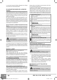
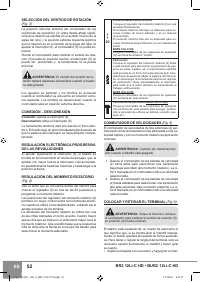
REVERSING
(Fig. 3)
The extreme position of forward/reverse switch (3) to
the right right (viewed from the rear) is equivalent to anti-
clockwise rotation, the extreme position to the left - to
clockwise rotation. When the ON/OFF switch (6) is de
-
pressed switch (3) cannot be actuated.
With the ON/OFF switch (3) in neutral position, switch (6)
cannot be pressed and the machine cannot be operated.
WARNING:
Reversing can be performed only
when the spindle is not rotating!
Drilling and tightening screws are performed with lever
in extreme position to the left. Removal of screws is per-
formed with lever in extreme position to the right.
SWITCHING ON - SWITCHING OFF
Switching on:
press ON/OFF switch (6).
Switching off:
release ON/OFF switch (6).
This power tool is equipped with electric brake. The spin-
dle stops rotating immediately after releasing the switch
lever.
SMOOTH ELECTRONIC RPM CONTROL
Light pressure on ON/OFF trigger switch (6) results in
low rotation speed, further pressing the switch results in
smooth increase of the rpm to maximum upon reaching
the extreme position.
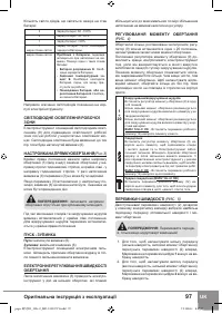
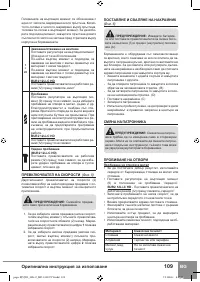
ADJUSTING THE TORQUE
(Fig. 4)
Rotate the torque adjustment collar (9) behind the chuck,
to adjust the torque to each of 20 settings.
The range of 20 torque settings allows better control
when using the drill as a screwdriver thus preventing
over-tightening of the screws.
The numbers circling the collar are used to indicate the
level of torque. The larger the number on the collar, the
higher the torque. To select any of the numbers, rotate
the collar (9) until the desired number aligns with the ar-
row head indicator on the housing of the machine.
1
÷
20
Screwdriving
Set the torque adjustment collar (9) against one of 20
positions.
Select low setting range for working with small screws
or in soft materials.
Select high setting range for working with large screws
or in hard materials.
BUR2 12Li-C HD:
Set the operation mode selector switch (12) against the
symbol “screw”.
pages B[U]R2_12Li-C_HD-133137V1.indd 8
7.2.2018 г. 8:47:33
Содержание
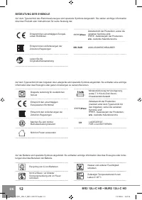
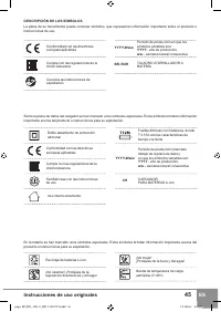
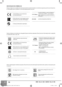
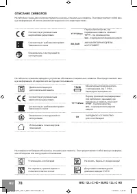
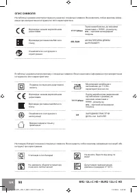
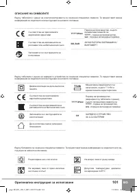
- 80 ОПИСАНИЕ СИМВОЛОВ
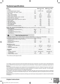
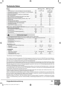
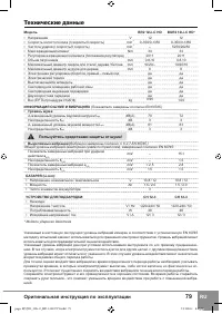
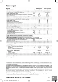
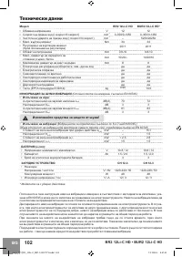
- 81 Технические данные; Пользуйтесь средствами защиты от шума!
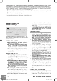
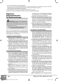
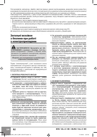
- 82 Общие указания по; БЕЗОПАСНОСТЬ РАБОЧЕГО МЕСТА
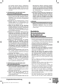
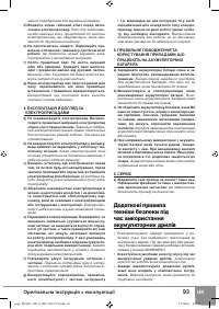
- 83 ЭКСПЛУАТАЦИЯ И УХОД ЗА
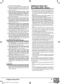
- 85 Дополнительные правила
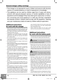
- 86 ПОДЗАРЯДКА БАТАРЕИ; Знакомство
- 87 Указания по работе
- 88 ПЕРЕКЛЮЧАТЕЛЬ ПЕРЕДАЧ
- 89 ЗАКРУЧИВАНИЕ / ОТКРУЧИВАНИЕ; Обслуживание; УДАЛЕНИЕ ЗАГРЯЗНЕНИЙ
- 90 Утилизация; Гарантия
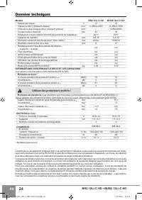
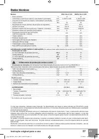
Характеристики

Остались вопросы?Не нашли свой ответ в руководстве или возникли другие проблемы? Задайте свой вопрос в форме ниже с подробным описанием вашей ситуации, чтобы другие люди и специалисты смогли дать на него ответ. Если вы знаете как решить проблему другого человека, пожалуйста, подскажите ему :)


