
Шуруповерты Makita DHP458Z LXT 18V - инструкция пользователя по применению, эксплуатации и установке на русском языке. Мы надеемся, она поможет вам решить возникшие у вас вопросы при эксплуатации техники.
Если остались вопросы, задайте их в комментариях после инструкции.
"Загружаем инструкцию", означает, что нужно подождать пока файл загрузится и можно будет его читать онлайн. Некоторые инструкции очень большие и время их появления зависит от вашей скорости интернета.

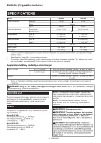


8 ENGLISH
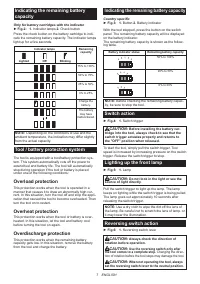
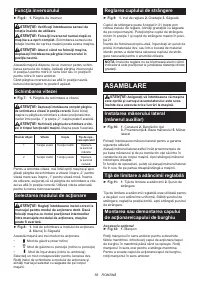
This tool has a reversing switch to change the direction
of rotation. Depress the reversing switch lever from the
A side for clockwise rotation or from the B side for coun
-
terclockwise rotation.
When the reversing switch lever is in the neutral posi-
tion, the switch trigger cannot be pulled.
Speed change
►
Fig.7:
1.
Speed change lever
CAUTION:
Always set the speed change lever
fully to the correct position.
If you operate the
tool with the speed change lever positioned halfway
between the "1" side and "2" side, the tool may be
damaged.
CAUTION:
Do not use the speed change lever
while the tool is running.
The tool may be damaged.
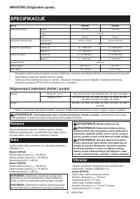
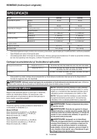
Displayed
Number
Speed
Torque
Applicable
operation
1
Low
High
Heavy load-
ing operation
2
High
Low
Light loading
operation
To change the speed, first switch off the tool and then
slide the speed change lever to the "2" side for high
speed or, "1" side for low speed. Be sure that the speed
change lever is set to the correct position before opera
-
tion. Use the right speed for your job.
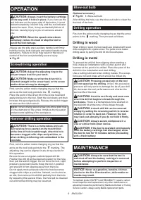
Selecting the action mode
CAUTION:
Always set the ring correctly to
your desired mode mark. If you operate the tool
with the ring positioned halfway between the
mode marks, the tool may be damaged.
►
Fig.8:
1.
Action mode changing ring
2.
Mark
3.
Arrow
This tool has three action modes.
•
Drilling mode (rotation only)
•
Hammer drilling mode (rotation with
hammering)
•
Screwdriving mode (rotation with clutch)
Select one mode suitable for your work. Turn the
action mode changing ring and align the mark that you
selected with the arrow on the tool body.
Adjusting the fastening torque
►
Fig.9:
1.
Adjusting ring
2.
Graduation
3.
Arrow
The fastening torque can be adjusted in 21 levels by
turning the adjusting ring. Align the graduations with the
arrow on the tool body. You can get the minimum fas
-
tening torque at 1 and maximum torque at 21.
Before actual operation, drive a trial screw into your
material or a piece of duplicate material to deter-
mine which torque level is required for a particular
application.
NOTE:
The adjusting ring does not lock when the
pointer is positioned only halfway between the
graduations.
ASSEMBLY
CAUTION:
Always be sure that the tool is
switched off and the battery cartridge is removed
before carrying out any work on the tool.
Installing side grip (auxiliary handle)
►
Fig.10:
1.
Groove
2.
Steel band
3.
Protrusion
4.
Grip base
5.
Side grip
Always use the side grip to ensure operating safety.
Attach the side grip so that the protrusions on the grip
base and steel band fit in the grooves on the tool barrel.
Then tighten the grip by turning clockwise.
Depending the operations, you can attach the side grip
upward or right/left side of the tool.
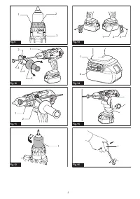
Adjustable depth rod
►
Fig.11:
1.
Depth rod
2.
Clamp screw
The adjustable depth rod is used to drill holes of uniform
depth. Loosen the clamp screw, set to desired position,
then tighten the clamp screw.
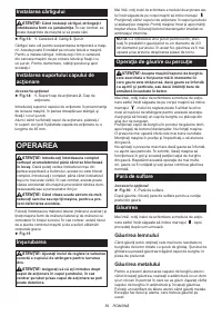
Installing or removing driver bit/
drill bit
Optional accessory
►
Fig.12:
1.
Sleeve
Turn the sleeve counterclockwise to open the chuck
jaws. Place the driver bit/drill bit in the chuck as far
as it will go. Turn the sleeve clockwise to tighten the
chuck. To remove the driver bit/drill bit, turn the sleeve
counterclockwise.
Installing hook
CAUTION:
When installing the hook, always
secure it with the screw firmly.
If not, the hook
may come off from the tool and result in the personal
injury.
►
Fig.13:
1.
Groove
2.
Hook
3.
Screw
The hook is convenient for temporarily hanging the tool.
This can be installed on either side of the tool. To install
the hook, insert it into a groove in the tool housing on
either side and then secure it with a screw. To remove,
loosen the screw and then take it out.
Installing driver bit holder
Optional accessory
►
Fig.14:
1.
Driver bit holder
2.
Driver bit
Fit the driver bit holder into the protrusion at the tool foot
on either right or left side and secure it with a screw.
When not using the driver bit, keep it in the driver bit
holders. Driver bits 45 mm-long can be kept there.
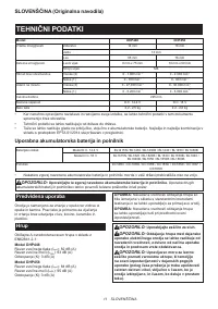
Характеристики

Остались вопросы?Не нашли свой ответ в руководстве или возникли другие проблемы? Задайте свой вопрос в форме ниже с подробным описанием вашей ситуации, чтобы другие люди и специалисты смогли дать на него ответ. Если вы знаете как решить проблему другого человека, пожалуйста, подскажите ему :)


