
Шуруповерты GRAPHITE 58G012-S15 - инструкция пользователя по применению, эксплуатации и установке на русском языке. Мы надеемся, она поможет вам решить возникшие у вас вопросы при эксплуатации техники.
Если остались вопросы, задайте их в комментариях после инструкции.
"Загружаем инструкцию", означает, что нужно подождать пока файл загрузится и можно будет его читать онлайн. Некоторые инструкции очень большие и время их появления зависит от вашей скорости интернета.


13
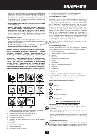
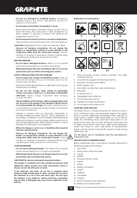
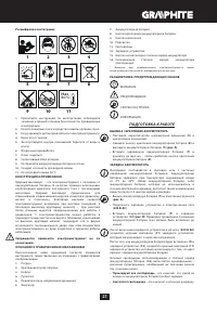
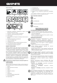
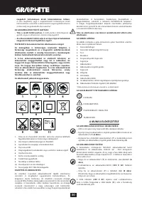
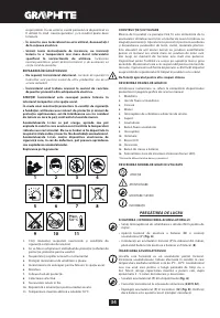
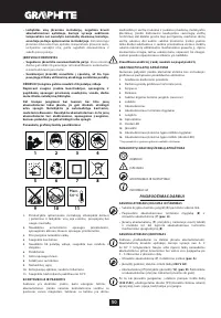
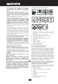
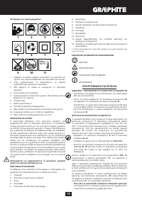
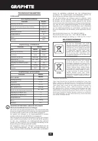
MEANING OF SYMBOLS
CAUTION
WARNING
ASSEMBLY / SET TINGS
INFORMATION
PREPARATION FOR OPERATION
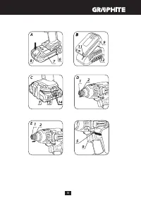
REMOVING AND INSERTING THE BAT TERY
•
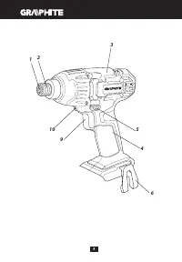
Set the direction selector switch (
5
) in middle position.
•
Push the battery lock button (
8
) and slide out the battery (
7
)
(
fig. A
).
•
Insert charged battery (
7
) into the handle holder, you should
hear when the battery lock button (
8
) snaps.
BAT TERY CHARGING
The device is supplied with partially charged battery. The battery
should be charged in ambient temperature between 4°C and
40°C. New battery, or one that has not been used for a long
time, will reach full efficiency after approximately 3 to 5 charge/
discharge cycles.
•
Remove the battery (
7
) from the device (
fig. A
).
•
Connect the charger to mains socket (230 V AC).
•
Slide the battery (
7
) into the charger (
12
) (
fig. B
). Ensure the
battery is properly fitted (pushed to the end).
When the charger is connected to a mains socket (
230 V AC
), the
green diode (
11
) on the charger turns on to indicate connected
supply.
When the battery (
7
) is placed in the charger (
12
), the red diode
(
11
) on the charger turns on to indicate that the charging is in
progress.
Simultaneously, green diodes (
14
) of the battery level indication
are flashing in different configurations, see description below.
• All diodes are flashing
- battery is empty and requires
charging.
• 2 diodes are flashing
- the battery is partially discharged.
• 1 diode is flashing
- the battery level is high.
Once the battery is charged, the diode (
11
) on the charger lights
green, and all battery level diodes (
14
) light continuously. After
some time (approx. 15 s) battery level indication diodes (
14
) turn
off.
Do not charge the battery for more than 8 hours. Exceeding
this time limit may cause damage to battery cells. The charger
will not turn off automatically when the battery is full. Green
diode on the charger will remain on. Battery level indication
diodes turn off after some time. Disconnect power supply
before removing the battery from the charger socket. Avoid
consecutive short chargings. Do not charge the battery after
short use of the tool. Significant decrease of the period
between chargings indicates the battery is used up and should
be replaced.
Batteries heat up when charging. Do not operate just
after charging – wait for the battery to cool down to room
temperature. It will prevent battery damage.
BAT TERY LEVEL INDICATION
The battery is equipped with signalisation of the battery level (3
LED diodes) (
14
). To check battery level status, press the button
for battery level indication (
13
) (
fig. C
). When all diodes are lit,
the battery level is high. When 2 diodes are on, the battery is
partially discharged. When only one diode is lit, the battery is
discharged and must be recharged.
SPINDLE BRAKE
Drill is equipped with electronic brake that stops the spindle
immediately after the switch button (
9
) is released. The brake
ensures precision when screwing or drilling and prevents free
spindle rotation after switching off.
OPERATION / SET TINGS
SWITCHING ON / SWITCHING OFF
Switching on
– press the switch button (
9
).
Switching off
– release the switch button (
9
).
Each time the switch button (
9
) is pressed, the LED diode (
10
)
lights up to illuminate the workplace.
ROTATIONAL SPEED CONTROL
Increase or reduce pressure on the switch button (
9
) to adjust
rotational speed while operating. Speed control allows for soft
start, which provides working control during tightening and
undoing bolts.
CIRCUMFERENTIAL IMPACT ACTION
The tool rotates the spindle when tightening, and creates
circumferential impact. Impact action actuates automatically
when the load increases. Then a high peak torque is applied.
Keep watching the screw or bolt for full control over tightening.
Keep control over tightening force by adjusting rotational speed.
WORKING TOOL INSTALLATION
•
Pull away the fixing sleeve of the tool chuck (
2
) (
fig. D
) against
the spring force.
•
Insert working tool shank into the tool chuck (
1
) and slide it in
to mechanical stop (it may be necessary to turn the working
tool so it can reach appropriate position).
•
Release the fixing sleeve of the tool chuck (
2
), it will finally lock
the working tool. The fixing sleeve of the tool chuck (
2
) will
return to its position (
fig. E
).
Deinstallation of the tool is similar to installation, only the
sequence of actions is reversed.
Use additional driver bit adapter with short driver bits.
RIGHT-LEFT DIRECTION OF ROTATION
Choose direction of spindle rotation with the direction selector
switch (
5)
(
fig. F
).
Clockwise rotation
– set the switch (
5
) to the extreme left
position.
Counter-clockwise rotation
– set the switch (
5
) to the extreme
right position.
* In certain cases position of the switch related to rotation may be different
than specified. Please refer to graphic signs located on the switch or tool
body.
Safe position of the direction selector switch (
5
) is in the middle,
it prevents accidental starting of the power tool.
•
When the switch is in this position, the power tool cannot be
started.
•
Use this position of the switch to change bits.
•
Before starting the tool make sure the position of the direction
selector switch (
5
) is correct.
Do not change direction of rotation when the spindle of the
power tool is rotating.
Long lasting operation at low rotational speed of the
spindle may cause motor overheating. Long lasting drilling
at low rotational speed of the spindle may cause motor
overheating.


