
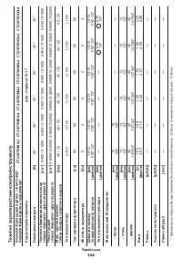
Шуруповерты CROWN CT21076HMX - инструкция пользователя по применению, эксплуатации и установке на русском языке. Мы надеемся, она поможет вам решить возникшие у вас вопросы при эксплуатации техники.
Если остались вопросы, задайте их в комментариях после инструкции.
"Загружаем инструкцию", означает, что нужно подождать пока файл загрузится и можно будет его читать онлайн. Некоторые инструкции очень большие и время их появления зависит от вашей скорости интернета.


32
English
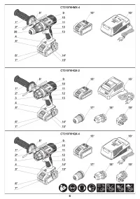
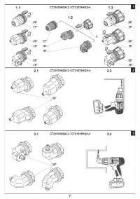
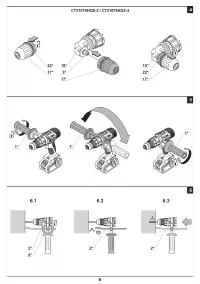
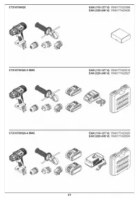
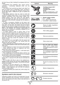
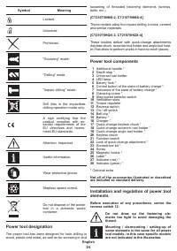
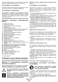
Mounting / replacement of quick-change accesso
-
ries (see fig. 1-3)
[CT21076HQX-2, CT21076HQX-4]
Quick-change attachments
17
,
18
or
19
enlarge the
area of power tool usage and allow to perform works in
hard-to-reach places (see fig. 2.2, 3.2).
•
Move the lock
22
forward and hold it in this position
(see fig. 1.1).
•
Install one of quick-change attachments
17
,
18
or
19
on universal tool holder
3
(see fig. 1.2).
•
Release the lock
22
(see fig. 1.3).
•
Disassembly operations do in reverse sequence�
•
Quick-change eccentric tool holder
18
can be set to
different positions (see fig. 2.1).
•
Quick-change angle tool holder
19
can be set to
different positions (see fig. 3.1).
•
Quick-change keyless chuck
17
(see fig. 4) can be
installed on quick-change angle tool holder
19
�
Additional handle (see fig. 5)
It's recommended use the additional handle
1
when
operating� Additional handle
1
may be positioned as
deemed comfortable by the user�
•
Loose additional handle
1
as shown in fig. 5.
•
Place additional handle
1
in desired position�
•
Tighten additional handle
1
as shown in fig. 5.
Depth stop (see fig. 6)
Use depth stop
2
to set a required drilling depth (see fig. 6).
•
Slacken clamping screw
8
(see fig. 6.1).
•
Touch the wall with the end of the drill bit and move
the depth stop
2
until its end touches the wall, as
shown in figure 6.1.
•
Move depth stop
2
back to set a required drilling
depth (distance "a") (see fig. 6.2).
•
Tighten clamping screw
8
and drill the hole (see
fig. 6.3).
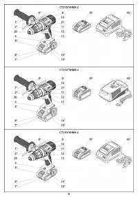
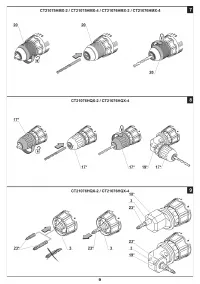
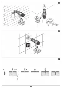
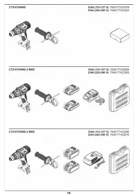
Mounting / replacement of accessories (see fig. 7-9)
[CT21075HMX-2, CT21075HMX-4, CT21076HMX-2,
CT21076HMX-4]
With long-term use the drill bit may be
-
come very warm; use gloves to remove it.
•
Open the jaws of the keyless chuck
20
, rotating its
front part as shown in fig. 7.
•
Mount / replace the accessory�
•
Tighten the keyless chuck
20
without skewing the
accessory as it is shown in fig. 7.
[CT21076HQX-2, CT21076HQX-4]
•
When installed quick-change keyless chuck 17:
•
Open the jaws of the keyless chuck
17
, rotating its
front part as shown in fig. 8.
•
Mount / replace the accessory�
•
Tighten the keyless chuck
17
without skewing the
accessory as it is shown in fig. 8.
•
When installed universal tool holder 3:
•
Mount / replace the screwdriver bit
23
into
universal tool holder
3
, as shown onto fig. 9.
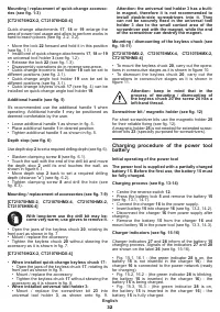
Attention: the universal tool holder 3 has a built-
in magnet, therefore it is not recommended to
install double-side screwdrivers into it. They
can not be securely fixed in the universal tool
holder 3 due to the small contact area of the
screwdriver end with the magnet, while the end
of the screwdriver can destroy the magnet.
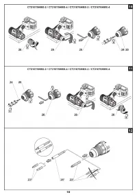
Mounting / dismounting of the keyless chuck (see
fig. 10-11)
[CT21075HMX-2, CT21075HMX-4, CT21076HMX-2,
CT21076HMX-4]
•
To mount the keyless chuck
20
, carry out the opera-
tions in consecutive stages as it is shown in figure 10.
•
To dismount the keyless chuck
20
, carry out the
operations in consecutive stages as it is shown in
figure 11.
Attention: keep in mind that in the
process of mounting / dismounting of
the keyless chuck 20 the screw 24 has a
left-hand thread.
Screwdriver bit / magnetic holder (see fig. 12)
For short screwdriver bits use the magnetic holder
25
for their reliable fixing (see fig. 12).
A magnetic holder
25
is not needed for extended screw-
driver bits
23
(specially purposed for screwdrivers)�
Charging procedure of the power tool
battery
Initial operating of the power tool
The power tool is supplied with a partially charged
battery 15. Before the first use, the battery 15 must
be fully charged.
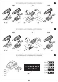
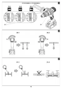
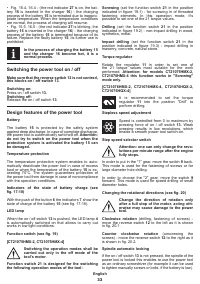
Charging process (see fig. 13-14)
•
Centre the reverse switch
12
�
•
Press the battery lock
5
and remove the battery
15
(see fig. 13.1, 14.1).
•
Connect the charger
16
to the power supply�
•
Insert battery
15
into charger
16
(see fig. 13.2, 14.2).
•
Disconnect the charger
16
from power supply after
charging�
•
Remove the battery
15
from the charger
16
and
mount battery
15
in the power tool (see fig. 13.3, 14.3).
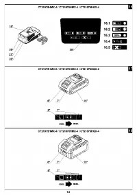
Charger indicators (see fig. 15-16)
Charger indicators
27
and
28
inform of the battery
15
charging process� Signals of the indicators
27
and
28
are shown on the label
26
(see fig. 15-16).
•
Fig� 15�1, 16�1 - (the green indicator
28
is on, the
battery
15
is not inserted in the charger
16
) - the
charger
16
is connected to the power network (ready
for charging)�
•
Fig� 15�2, 16�2 - (the green indicator
28
is blinking,
the battery
15
is inserted in the charger
16
) - the
battery
15
is being charged�
•
Fig� 15�3, 16�3 - (the green indicator
28
is on,
the battery
15
is inserted in the charger
16
) - the
battery
15
is fully charged�


