
Шуруповерты CROWN CT21072HX-2 BMC - инструкция пользователя по применению, эксплуатации и установке на русском языке. Мы надеемся, она поможет вам решить возникшие у вас вопросы при эксплуатации техники.
Если остались вопросы, задайте их в комментариях после инструкции.
"Загружаем инструкцию", означает, что нужно подождать пока файл загрузится и можно будет его читать онлайн. Некоторые инструкции очень большие и время их появления зависит от вашей скорости интернета.


26
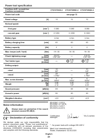
English
•
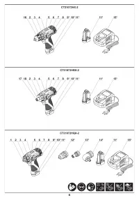
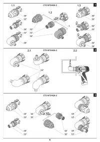
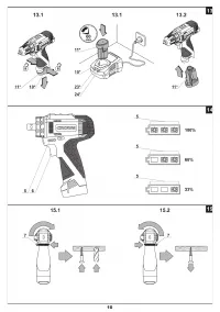
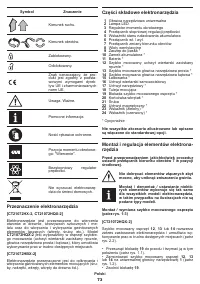
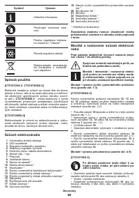
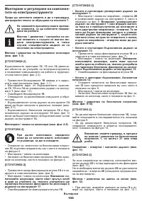
Mount / replace the accessory�
Attention: use
accessories that have circular groove at the
stem end, their use will guarantee safe fixation
of accessory in the quick-change tool holder 13.
•
Release the fixing bush
18
�
•
When installed quick-change keyless chuck 12:
•
Open the jaws of the keyless chuck
12
, rotating its
front part as shown in fig. 8.
•
Mount / replace the accessory�
•
Tighten the keyless chuck
12
without skewing the
accessory as it is shown in fig. 8.
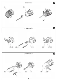
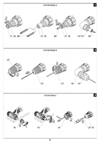
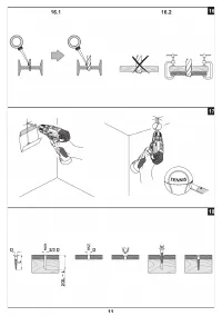
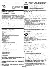
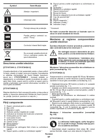
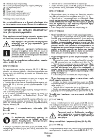
Mounting / dismounting of the keyless chuck (see
fig. 9-10)
[CT21072HX-2]
•
To mount the keyless chuck
16
, carry out the
operations in consecutive stages as it is shown in
figure 9.
•
To dismount the keyless chuck
16
, carry out the
operations in consecutive stages as it is shown in
figure 10.
Attention: keep in mind that in the
process of mounting / dismounting of
the keyless chuck 1 the screw 21 has a
left-hand thread.
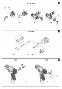
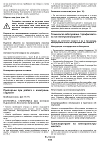
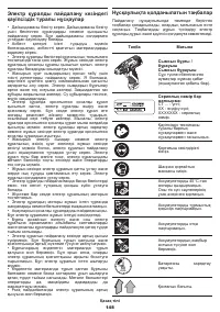
Screwdriver bit / magnetic holder (see fig. 11)
[CT21072HX-2]
For short screwdriver bits use the magnetic holder
22
for their reliable fixing (see fig. 11).
A magnetic holder
22
is not needed for extended
screwdriver bits
20
(specially purposed for screwdriv-
ers)�
Mounting / dismounting of the belt clip (see fig. 12)
•
When installing insert belt clip
9
into the opening on
a housing as shown on fig. 12.1. The spring lock of belt
clip
9
shall be locked in place�
•
When dismantling by means of a flat screwdriver
press the spring lock of belt clip
9
and pull it out (see
fig. 12.2).
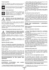
Charging procedure of the power tool
battery
Initial operating of the power tool
The power tool is supplied with a partially charged
battery 11. Before the first use, the battery 11 must
be fully charged.
Charging process (see fig. 13)
•
Centre the reverse switch
7
�
•
Press the two battery lock
10
and remove the
battery
11
(see fig. 13.1).
•
Insert battery
11
into charger
15
(see fig. 13.2).
•
Connect the charger
15
to the power supply�
•
Charger indicators
23
(green) and
24
(red) inform of
the battery
11
charging process�
•
The green indicator
23
is lit, the battery
11
is
not inserted in the charger
15
- the charger
15
is
connected to the power network (ready for charging)�
•
The green indicator
23
is blinking, the battery
11
is inserted in the charger
15
- the battery
11
is being
charged�
•
The green indicator
23
is lit, the battery
11
is inserted
in the charger
15
- the battery
11
is fully charged�
•
The red indicator
24
is lit, the battery
11
is
inserted in the charger
15
- the charging process
of the battery
11
is terminated due to inappropriate
temperature� When the temperature conditions are
normal, the process of charging will resume�
•
The red indicator
24
is blinking, the battery
11
is
inserted in the charger
15
- the charging process of
the battery
11
is terminated because of its failure�
Replace the faulty battery
11
, its further use is
prohibited�
In the process of charging the battery 11
and the charger 15 become hot, it is a
normal process.
•
Disconnect the charger
15
from power supply after
charging�
•
Remove the battery
11
from the charger
15
and
mount battery
11
in the power tool (see fig. 13.3).
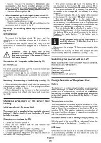
Switching the power tool on / off
Make sure that the reverse switch 7 is not centred,
this blocks on / off switch 6.
Switching on:
Press on / off switch
6.
Switching off:
Release the on / off switch
6
�
Design features of the power tool
Battery
The battery
11
is protected by the safety system against
deep discharge� In case of complete discharge, the
power tool is automatically switched off�
Attention:
do not try to switch on the power tool when the
protection system is activated the battery 11 can
be damaged.
Temperature protection
The temperature protection system enables to auto-
matically deactivate the power tool in case of excess
load or when the temperature of the battery
11
is ex-
ceeding 70°C� The system guarantees protection of
the power tool from damage in case of noncompliance
with the operation conditions�
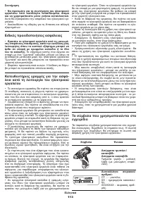
Indicators of the state of battery charge (see fig. 14)
With the push of the on / off
6
the indicators
5
show the
state of charge of the battery
11
(see fig. 14).
LED lamp
When the on / off switch
6
is pushed, the LED lamp
2
is automatically switched on that allows to carry out
works in low light conditions�


