
Шлифмашины Makita GA005GM201 - инструкция пользователя по применению, эксплуатации и установке на русском языке. Мы надеемся, она поможет вам решить возникшие у вас вопросы при эксплуатации техники.
Если остались вопросы, задайте их в комментариях после инструкции.
"Загружаем инструкцию", означает, что нужно подождать пока файл загрузится и можно будет его читать онлайн. Некоторые инструкции очень большие и время их появления зависит от вашей скорости интернета.


14 ENGLISH
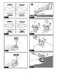
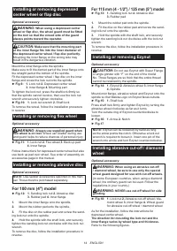
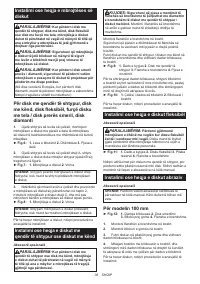
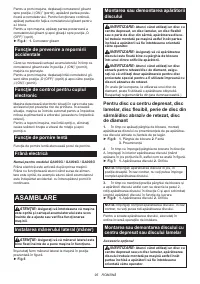
Installing or removing depressed
center wheel or flap disc
Optional accessory
WARNING:
When using a depressed center
wheel or flap disc, the wheel guard must be fitted
on the tool so that the closed side of the guard
always points toward the operator.
CAUTION:
Make sure that the mounting part
of the inner flange fits into the inner diameter of
the depressed center wheel / flap disc perfectly.
Mounting the inner flange on the wrong side may
result in the dangerous vibration.
Mount the inner flange onto the spindle.
Make sure to fit the dented part of the inner flange onto
the straight part at the bottom of the spindle.
Fit the depressed center wheel / flap disc on the inner
flange and screw the lock nut onto the spindle.
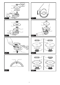
►
Fig.9:
1.
Lock nut
2.
Depressed center wheel
3.
Inner flange
4.
Mounting part
To tighten the lock nut, press the shaft lock firmly so
that the spindle cannot revolve, then use the lock nut
wrench and securely tighten clockwise.
►
Fig.10:
1.
Lock nut wrench
2.
Shaft lock
To remove the wheel, follow the installation procedure
in reverse.
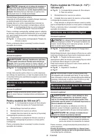
Installing or removing flex wheel
Optional accessory
WARNING:
Always use supplied guard when
flex wheel is on tool.
Wheel can shatter during use
and guard helps to reduce chances of personal injury.
►
Fig.11:
1.
Lock nut
2.
Flex wheel
3.
Back up pad
4.
Inner flange
Follow instructions for depressed center wheel but also
use back up pad over wheel. See order of assembly on
accessories page in this manual.
Installing or removing abrasive disc
Optional accessory
NOTE:
Use sander accessories specified in this man
-
ual. These must be purchased separately.
For 100 mm (4″) model
►
Fig.12:
1.
Sanding lock nut
2.
Abrasive disc
3.
Rubber pad
4.
Inner flange
1.
Mount the inner flange onto the spindle.
2.
Mount the rubber pad onto the spindle.
3.
Fit the disc on the rubber pad and screw the sand
-
ing lock nut onto the spindle.
4.
Hold the spindle with the shaft lock, and securely
tighten the sanding lock nut clockwise with the lock nut
wrench.
To remove the disc, follow the installation procedure in
reverse.
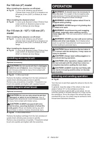
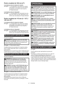
For 115 mm (4 - 1/2″) / 125 mm (5″) model
►
Fig.13:
1.
Sanding lock nut
2.
Abrasive disc
3.
Rubber pad
1.
Mount the rubber pad onto the spindle.
2.
Fit the disc on the rubber pad and screw the sand
-
ing lock nut onto the spindle.
3.
Hold the spindle with the shaft lock, and securely
tighten the sanding lock nut clockwise with the lock nut
wrench.
To remove the disc, follow the installation procedure in
reverse.
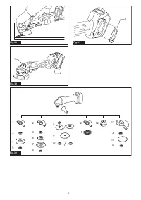
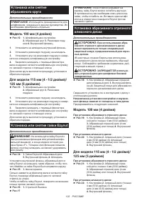
Installing or removing Ezynut
Optional accessory
CAUTION:
Do not use Ezynut with Super Flange
or angle grinder with “F” on the end of the model
No. Those flanges are so thick that the entire thread
cannot be retained by the spindle.
►
Fig.14:
1.
Ezynut
2.
Abrasive wheel
3.
Inner flange
4.
Spindle
Mount inner flange, abrasive wheel and Ezynut onto the
spindle so that Makita Logo on Ezynut faces outside.
►
Fig.15:
1.
Shaft lock
Press shaft lock firmly and tighten Ezynut by turning the
abrasive wheel clockwise as far as it turns.
Turn the outside ring of Ezynut counterclockwise to
loosen.
►
Fig.16:
1.
Arrow
2.
Notch
►
Fig.17
NOTE:
Ezynut can be loosened by hand as long
as the arrow points the notch. Otherwise a lock nut
wrench is required to loosen it. Insert one pin of the
wrench into a hole and turn Ezynut counterclockwise.
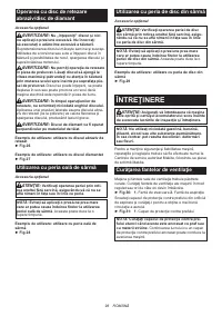
Installing abrasive cut-off / diamond
wheel
Optional accessory
WARNING:
When using an abrasive cut-off
/ diamond wheel, be sure to use only the special
wheel guard designed for use with cut-off wheels.
(In some European countries, when using a diamond
wheel, the ordinary guard can be used. Follow the
regulations in your country.)
WARNING:
NEVER use cut-off wheel for side
grinding.
►
Fig.18:
1.
Lock nut
2.
Abrasive cut-off wheel / dia
-
mond wheel
3.
Inner flange
4.
Wheel guard
for abrasive cut-off wheel / diamond wheel
As for the installation, follow the instructions for
depressed center wheel.
The direction for mounting the lock nut and the
inner flange varies by wheel type and thickness.
Refer to the following figures.
Содержание
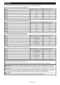
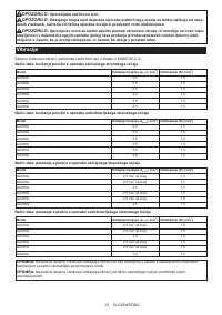
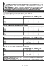
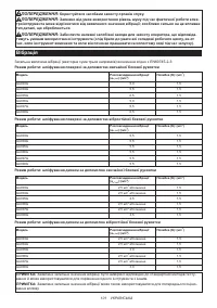
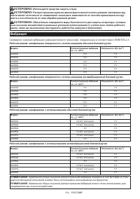
- 114 Вибрация
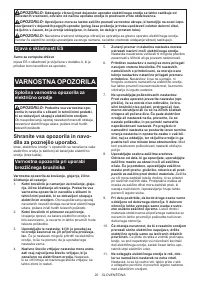
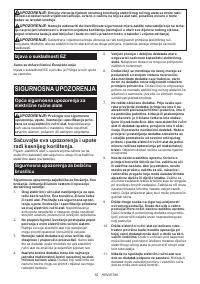
- 115 МЕРЫ БЕЗОПАСНОСТИ; Сохраните брошюру с инструк
- 118 СОХРАНИТЕ ДАННЫЕ; Важные правила техники
- 119 ОПИСАНИЕ РАБОТЫ; Установка или снятие блока
- 120 Защита от перегрузки
- 121 СБОРКА; Установка или снятие кожуха диска; Установка и снятие гибкого диска
- 122 Установка или снятие; Установка или снятие гайки Ezynut; Установка абразивного отрезного/
- 123 Установка чашечной проволочной щетки; Установка дисковой проволочной щетки; ЭКСПЛУАТАЦИЯ; Шлифовка и зачистка
- 124 ОБСЛУЖИВАНИЕ
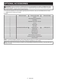
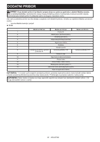
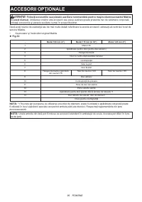
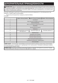
- 125 ДОПОЛНИТЕЛЬНЫЕ ПРИНАДЛЕЖНОСТИ
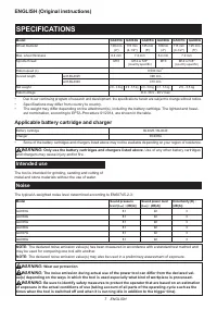
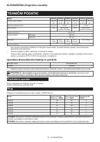
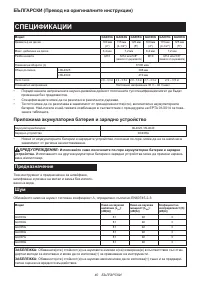
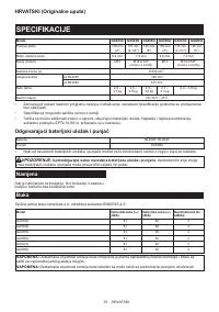
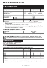
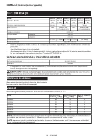
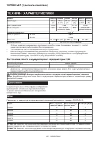
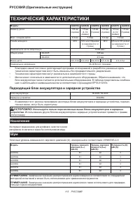
Характеристики

Остались вопросы?Не нашли свой ответ в руководстве или возникли другие проблемы? Задайте свой вопрос в форме ниже с подробным описанием вашей ситуации, чтобы другие люди и специалисты смогли дать на него ответ. Если вы знаете как решить проблему другого человека, пожалуйста, подскажите ему :)


