
Шлифмашины Makita GA005GM201 - инструкция пользователя по применению, эксплуатации и установке на русском языке. Мы надеемся, она поможет вам решить возникшие у вас вопросы при эксплуатации техники.
Если остались вопросы, задайте их в комментариях после инструкции.
"Загружаем инструкцию", означает, что нужно подождать пока файл загрузится и можно будет его читать онлайн. Некоторые инструкции очень большие и время их появления зависит от вашей скорости интернета.


13 ENGLISH
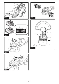
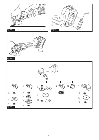
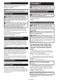
Shaft lock
Press the shaft lock to prevent spindle rotation when
installing or removing accessories.
►
Fig.3:
1.
Shaft lock
NOTICE:
Never actuate the shaft lock when the
spindle is moving.
The tool may be damaged.
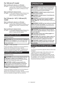
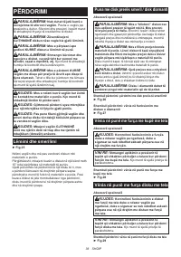
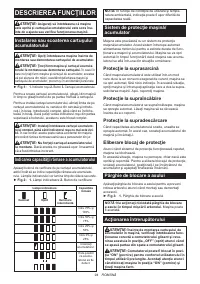
Switch action
CAUTION:
Before installing the battery car
-
tridge into the tool, always check to see that the
slide switch actuates properly and returns to the
"OFF" position when the rear of the slide switch
is depressed.
CAUTION:
Switch can be locked in "ON" posi
-
tion for ease of operator comfort during extended
use. Apply caution when locking tool in "ON"
position and maintain firm grasp on tool.
To start the tool, slide the slide switch toward the “I
(ON)” position by pushing the rear of the slide switch.
For continuous operation, press the front of the slide
switch to lock it.
To stop the tool, press the rear of the slide switch, then
slide it toward the “O (OFF)” position.
►
Fig.4:
1.
Slide switch
Accidental re-start preventive
function
When installing the battery cartridge while the slide
switch in the "I (ON)" position, the tool does not start.
To start the tool, first slide the slide switch toward the
"O (OFF)" position and then slide it toward the "I (ON)"
position.
Electronic torque control function
The tool electronically detects situations where the
wheel or accessory may be at risk to be bound. In the
situation, the tool is automatically shut off to prevent
further rotation of the spindle (it does not prevent
kickback).
To restart the tool, switch off the tool first, remove the
cause of sudden drop in the rotation speed, and then
turn the tool on.
Soft start feature
Soft start feature reduces starting reaction.
Electric brake
Only for model GA003G / GA004G / GA005G
Electric brake is activated after the tool is switched off.
The brake does not work when the power supply is shut
down, such as the battery is removed accidentally, with
the switch still on.
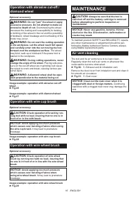
ASSEMBLY
CAUTION:
Always be sure that the tool is
switched off and the battery cartridge is removed
before adjusting or checking function on the tool.
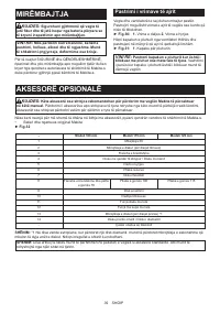
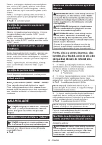
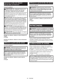
Installing side grip (handle)
CAUTION:
Always be sure that the side grip is
installed securely before operation.
Screw the side grip securely on the position of the tool
as shown in the figure.
►
Fig.5
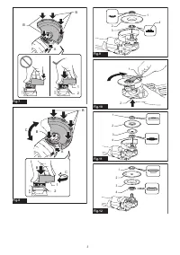
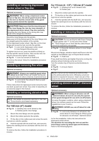
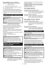
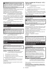
Installing or removing wheel guard
WARNING:
When using a depressed center
wheel, flap disc, flex wheel or wire wheel brush,
the wheel guard must be fitted on the tool so that
the closed side of the guard always points toward
the operator.
WARNING:
Make sure that the wheel guard is
securely locked by the lock lever with one of the
holes on the wheel guard.
WARNING:
When using an abrasive cut-off
/ diamond wheel, be sure to use only the special
wheel guard designed for use with cut-off wheels.
(In some European countries, when using a diamond
wheel, the ordinary guard can be used. Follow the
regulations in your country.)
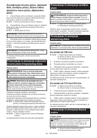
For depressed center wheel, flap
disc, flex wheel, wire wheel brush
/ abrasive cut-off wheel, diamond
wheel
1.
While pushing the lock lever, mount the wheel
guard with the protrusions on the wheel guard aligned
with the notches on the bearing box.
►
Fig.6:
1.
Lock lever
2.
Notch
3.
Protrusion
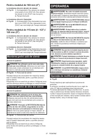
2.
While pushing the lock lever toward A, push in the
wheel guard by holding down the portions B as shown
in the figure.
►
Fig.7:
1.
Wheel guard
2.
Hole
NOTE:
Push down the wheel guard straight.
Otherwise, you cannot push the wheel guard
completely.
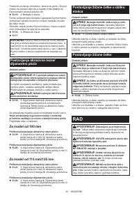
3.
While keeping the lock lever and wheel guard
position as described in step 2, rotate the wheel guard
toward C, and then, change the angle of the wheel
guard according to the work.
►
Fig.8:
1.
Wheel guard
2.
Hole
NOTE:
Push the wheel guard completely. Otherwise,
you cannot rotate the wheel guard.
To remove wheel guard, follow the installation proce-
dure in reverse.
Содержание
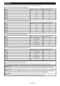
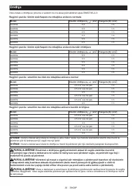
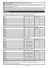
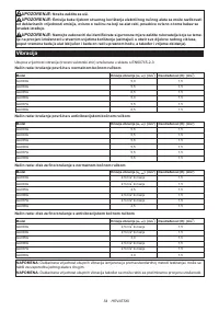
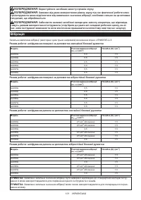
- 114 Вибрация
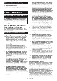
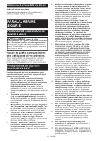
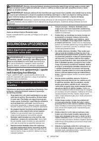
- 115 МЕРЫ БЕЗОПАСНОСТИ; Сохраните брошюру с инструк
- 118 СОХРАНИТЕ ДАННЫЕ; Важные правила техники
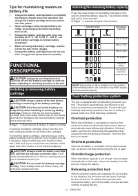
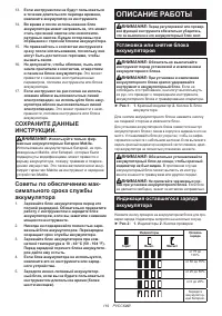
- 119 ОПИСАНИЕ РАБОТЫ; Установка или снятие блока
- 120 Защита от перегрузки
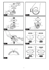
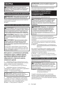
- 121 СБОРКА; Установка или снятие кожуха диска; Установка и снятие гибкого диска
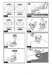
- 122 Установка или снятие; Установка или снятие гайки Ezynut; Установка абразивного отрезного/
- 123 Установка чашечной проволочной щетки; Установка дисковой проволочной щетки; ЭКСПЛУАТАЦИЯ; Шлифовка и зачистка
- 124 ОБСЛУЖИВАНИЕ
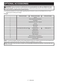
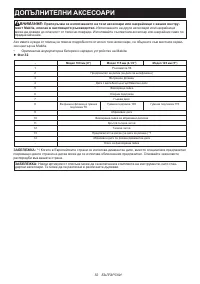
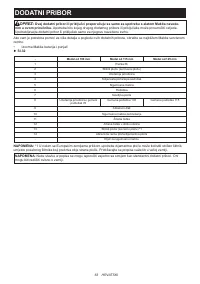
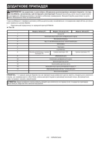
- 125 ДОПОЛНИТЕЛЬНЫЕ ПРИНАДЛЕЖНОСТИ
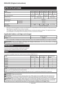
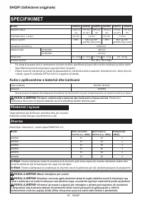
Характеристики

Остались вопросы?Не нашли свой ответ в руководстве или возникли другие проблемы? Задайте свой вопрос в форме ниже с подробным описанием вашей ситуации, чтобы другие люди и специалисты смогли дать на него ответ. Если вы знаете как решить проблему другого человека, пожалуйста, подскажите ему :)


