Пилы дисковые Energy 58G008 - инструкция пользователя по применению, эксплуатации и установке на русском языке. Мы надеемся, она поможет вам решить возникшие у вас вопросы при эксплуатации техники.
Если остались вопросы, задайте их в комментариях после инструкции.
"Загружаем инструкцию", означает, что нужно подождать пока файл загрузится и можно будет его читать онлайн. Некоторые инструкции очень большие и время их появления зависит от вашей скорости интернета.


16
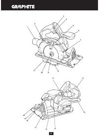
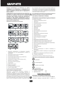
7.
Lighting
8.
Cutting blade
9.
Flange washer
10.
Fixing bolt for cutting blade
11.
Lower guard
12.
Cutting depth guide
13.
Main handle
14.
Batter y installation socket
15.
Spindle lock button
16.
Footplate
17.
Knob for base bevel adjustment
18.
Cutting line indicator for 45°
19.
Cutting line indicator for 0°
20.
Edge guide locking screw
21.
Batter y lock button
22.
Batter y
23.
Charger
24.
LED diodes
25.
Button for batter y level indication
26.
Batter y level indicator (LED)
27.
Cutting depth locking knob
28.
Edge guide
*Differences may appear between the product and drawing.
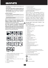
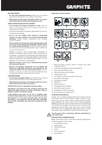
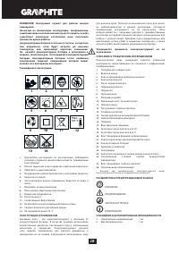
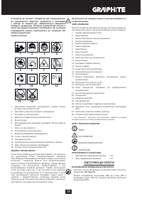
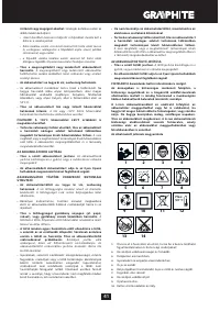
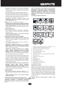
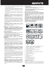
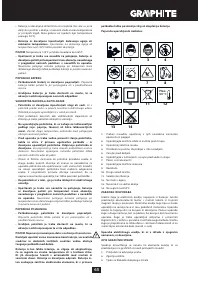
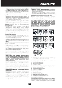
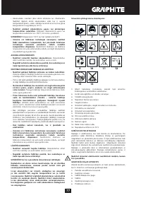
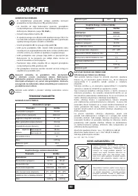
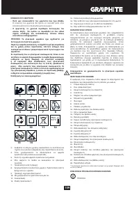
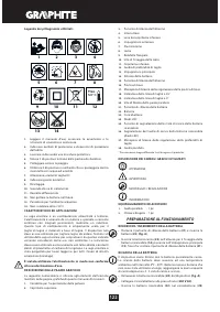
M E A N I N G O F S YM B O L S
CAUTION
WARNING
ASSEMBLY / SET TINGS
INFORMATION
EQUIPMENT AND ACCESSORIES
1.
Edge guide
- 1 pce
2.
Hexagonal key
- 1 pce
PREPARATION FOR OPERATION
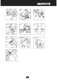
REMOVING AND INSERTING THE BAT TERY
•
Push the batter y lock button (
21
) and slide out the batter y (
22
)
(
fig. A
).
•
Inser t charged batter y (
22
) into the batter y installation socket
(
14
) in the main handle (
13
), you should hear when the batter y
lock button (
21
) snaps.
BAT TERY CHARGING
The device is supplied with par tially charged batter y. The batter y
should be charged in ambient temperature between 4°C and
40°C. New batter y, or one that has not been used for a long
time, will reach full efficiency after approximately 3 to 5 charge/
discharge cycles.
•
Remove the batter y (
22
) from the device (
fig. A
).
•
Connect the charger to mains socket (
230 V AC
).
•
Slide the batter y (
22
) into the charger (
23
) (
fig. B
). Ensure the
batter y is properly fitted (pushed to the end).
When the charger is connected to a mains socket (
230 V AC
), the
green diode (
24
) on the charger turns on to indicate connected
supply.
When the batter y (
22
) is placed in the charger (
23
), the red diode
(
24
) on the charger turns on to indicate that the charging is in
progress.
At the same time green diodes (
26
) of the batter y level indication
are flashing in different configurations, see description below.
• All diodes are flashing
- batter y is empty and requires
charging.
• 2 diodes are flashing
- the batter y is par tially discharged.
• 1 diode is flashing
- the batter y level is high.
Once the batter y is charged, the diode (
24
) on the charger lights
green, and all batter y level diodes (
26
) light continuously. After
some time (approx. 15 s) batter y level indication diodes (
26
) turn
off.
Do not charge the batter y for more than 8 hours. Exceeding
this time limit may cause damage to batter y cells. The charger
will not turn off automatically when the batter y is full. Green
diode on the charger will remain on. Batter y level indication
diodes turn off after some time. Disconnect power supply
before removing the batter y from the charger socket. Avoid
consecutive shor t chargings. Do not charge the batter y after
shor t use of the tool. Significant decrease of the period
between chargings indicates the batter y is used up and should
be replaced.
Batteries heat up strongly when charging. Do not operate just
after charging – wait for the batter y to cool down to room
temperature. It will prevent batter y damage.
BAT TERY LE VEL INDIC ATION
The batter y is equipped with indication of the batter y level (3
LED diodes) (
26
). To check batter y level status, press the switch
button (
25
) (
fig. C
). When all diodes are lit, the batter y level is
high. When 2 diodes are on, the batter y is par tially discharged.
When only one diode is lit, the batter y is discharged and must
be recharged.
C U T T I N G D E P T H A D J U S T M E N T
Right angle cutting depth can be set from the range of 0 to 46 mm.
•
Loosen the cutting depth locking knob (
27
).
•
Set desired cutting depth (use the scale).
•
Lock the cutting depth locking knob (
27
) (
fig. D
).
INSTALLATION OF THE EDGE GUIDE
Edge guide can be installed on left or right side of the device
footplate.
•
Loosen the edge guide locking screw (
20
).
•
Slide the edge guide bar into holes in the footplate (
16
), use the
scale to set required distance and fix by tightening the edge guide
locking screws (
20
) (
fig. E
).
Edge guide bar should be pointed downwards.
The edge guide (
28
) can also be used for bevel cutting at angles
ranging from 0° to 45°.
Never put hand or fingers behind the working saw. When kick
back happens the saw can fall on the hand, it may be the cause
of heavy body injury.
M OV I N G T H E LOW E R G UA R D
Lower guard (
11
) of the cutting blade (
8
) is pushed away
automatically as the blade sinks into the material. To remove it
manually push the lower guard lever (
5
).
D U S T E X T R AC T I O N
Circular saw is equipped with dust extraction outlet (
1
) that allows
for extraction of sawdust produced when cutting.
OPERATION / SETTINGS
SWITCHING ON / SWITCHING OFF
Hold the saw with both hands when starting up, because engine
torque may cause uncontrolled turn of the power tool.
Remember that rotating parts of the saw rotate for some time
after the tool has been switched off.
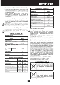
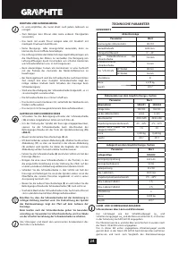
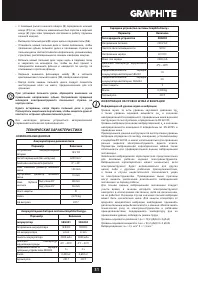
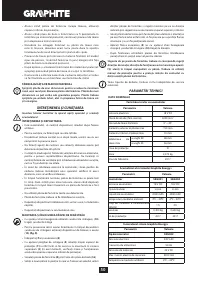
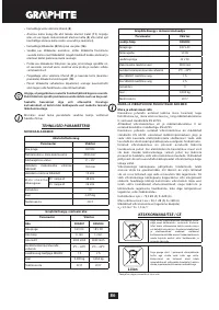
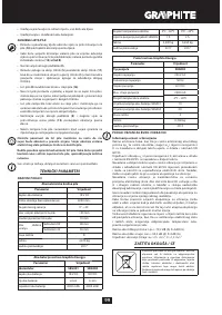
Характеристики

Остались вопросы?Не нашли свой ответ в руководстве или возникли другие проблемы? Задайте свой вопрос в форме ниже с подробным описанием вашей ситуации, чтобы другие люди и специалисты смогли дать на него ответ. Если вы знаете как решить проблему другого человека, пожалуйста, подскажите ему :)


