
Обогреватели Atlantic F 17 1500 - инструкция пользователя по применению, эксплуатации и установке на русском языке. Мы надеемся, она поможет вам решить возникшие у вас вопросы при эксплуатации техники.
Если остались вопросы, задайте их в комментариях после инструкции.
"Загружаем инструкцию", означает, что нужно подождать пока файл загрузится и можно будет его читать онлайн. Некоторые инструкции очень большие и время их появления зависит от вашей скорости интернета.
The product you have just purchased has undergone numerous tests and inspections to guarantee the highest quality. We hope it will give you entire
satisfaction.
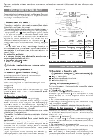
INSTALLATION OF THE PANEL HEATER
Please read the instructions before starting to install the heater. Disconnect
the power before carrying out any work on the heater. Keep these instructions
even once you have installed your heater.
1) Where to install your heater ?
- This equipment was designed to be installed in a residence. Please ask your
distributor before using it for any other purpose.
- The panel heater should be installed according to normal trade practice and in
compliance with legislation in the relevant country (the IEE Wiring Regulations).
- The equipment is class 2
and is protected against splashed water IP
24. The device is to be installed so that switches and other controls cannot
be touched by a person in the bath or shower, except in the UK where IEE
Regulations 701.512.2 and 701.512.3 apply. These allow the use of IP24
rated products and their integral controls in Zone 2 and outside zones.
- Comply with the minimum clearance distances for positioning of the panel
heater.
- If your wall covering is laid on foam, a spacer the same thickness as the
foam must be placed under the panel heater’s support. This ensures there is
free space behind the panel heater to make sure its control settings are not
adversely affected.
- Do not install the panel heater:
F
In a draught that might affect adjustment (for example, under a
central mechanical ventilation unit etc...).
F
Under a
fi
xed mains power socket.
F
In zone 1 of bathrooms
.
It is forbiden to install vertical product in horizontal position.
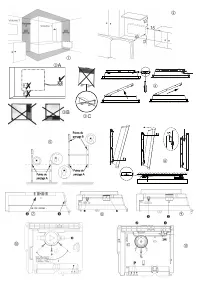
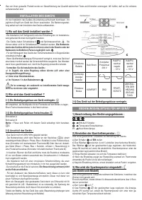
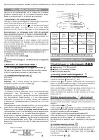
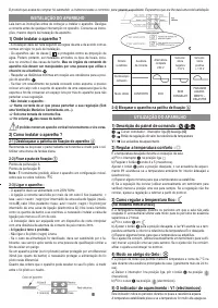
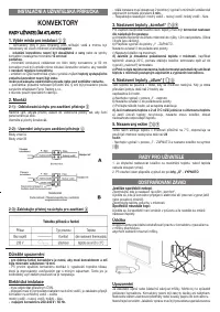
2) How to install the panel heater ?
2-1) Release the appliance’s hook-on bracket
We recommend that you place the radiant panel
fl
at, face down.
Have a straight head screwdriver to hand.
2-2) Fix the hook-on bracket
Use the wall-mounting bracket as a template for positioning the heater.
Drilling points A
Drilling points B
Note :
Do not use the device in mobile or feets or on casters
C, except
the range kit feet (ref. 417010 - 417015 - 417020) and Australian ranges :
Standard and Low.
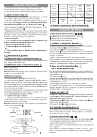
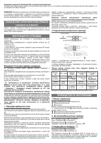
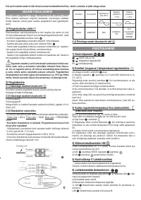
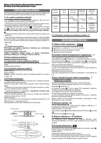
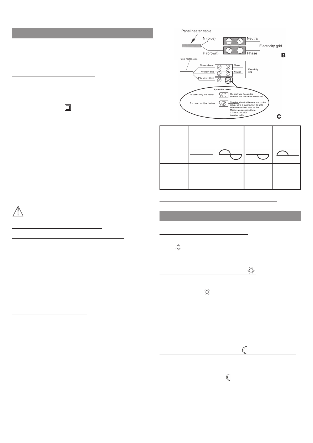
2-3) Connecting the panel heater
- The appliance should have a 230-240V 50Hz power supply.
- The panel heater must be connected to the mains, either by a 2-wire cable
(Brown = Phase, Blue = Neutral) via a power socket (Product with plug :
diagram
A
) or connexion box (Mechanical thermostat : diagram
B
) ; by a
3-wire cable (Brown= Phase, Blue = Neutral, Black = Pilot wire) by means of
a connexion box (version with pilote wire : diagram
C
).
In humid areas such as bathrooms and kitchens the power socket must be
installed at least 25 cm above the
fl
oor.
- The installation should be
fi
tted with a double pole break device with a break
of at least 3 mm.
- Connection to earth is prohibited. Do not connect the pilot wire
(black) to earth.
- The heater must be installed by a quali
fi
ed electrician in accordance with
the local regulations. The heater and the pilot wire (black) must
NOT
be
connected to earth. If the power cable is damaged, it must be replaced by
the manufacturer or its after-sales service Department or a similary quali
fi
ed
person to avoid any risk.
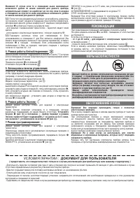
If a pilot or piloted panel heater is protected by 30mA differential (e.g.
bathroom) the pilot wire’s power must be protected on this differential
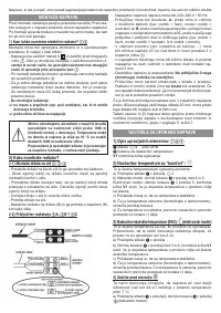
Commands
Received
No current
Complete
altermation
230 V
Négative
Half/altermation
- 115 V
Positive
Half/altermation
+ 115 V
Oscilloscope
Réf/Neutral
Mode
obtained
COMFORT
ECO
ANTI-
FREEZE
STOP
HEATING –
LOAD
SHEDDING
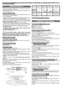
2-4) Lock the appliance on the hook-on bracket
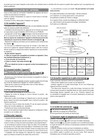
USING THE PANEL HEATER
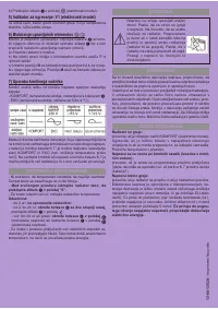
1) Description of the control unit :
(mecanical model) and
(electronic model)
J
/I switch (stop/0).
J
Temperature adjustment control knob.
V1
J
Heating indicator light
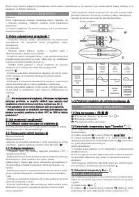
2) Fixing the comfort temperature
The comfort temperature is the temperature that you would like while the
room is occupied.
a) Put the
switch to
(marche/I).
b) Mechanical : set the
control knob to between 4 and 5.
Electronical : ajust the control knob
to the wished position, the heating
indicator
V1
comes on if the room temperature is below the required
temperature.
c) Wait a few hours for the temperature to stabilise.
d) If the setting is satisfactory (if necessary use a thermometer to check),
mark the position for future use.
e) If the setting is not satisfactory, adjust it and start again from point
c
.
3) Fixing the Eco temperature : (electronic model)
This is the required temperature during periods when the room is unoccupied.
It is recommended that this mode should be used if the room is unoccupied
for more than 2 hours.
a) Set the cursor
switch knob to .
b) Ajust the control knob
to the wished position, the heating light
V1
comes on, if the ambient temperature is lower than the instruction of desired
Eco temperature.
c) Wait a few hours until the temperature stabilizes.
d) If the setting is satisfactory (if necessary use a thermometer to check),
mark the position.
If the setting is not satisfactory, adjust it and start again from point
c
.
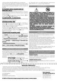
Note :
When switching n°1 (
on the picture
) is set on Programming system
(clock symbol)
with the PassProgram On/Off, please refer to paragraph n°8.
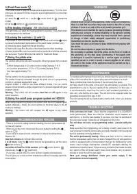
4) Fro
This m
when y
24 hou
a) Lea
model)
b) Set
5) Th
This lig
the tem
6) Lo
It is pos
to prev
a) Unh
b) Rem
c) Sele
can be
7) Us
The pr
unit :
- comf
- eco (
- frost
- off.
Put the
The pr
control
progra
severa
progra
Warnin
switch
8) Us
When
system
mode (
Warnin
selectio
- There
not rise
- When
switch
- If you
Absenc
less th
2 to 24
swi
more t
(mecan
- If you
This w
consum
Характеристики

Остались вопросы?Не нашли свой ответ в руководстве или возникли другие проблемы? Задайте свой вопрос в форме ниже с подробным описанием вашей ситуации, чтобы другие люди и специалисты смогли дать на него ответ. Если вы знаете как решить проблему другого человека, пожалуйста, подскажите ему :)


