
Мультиметры Wurth TRMS 071553 415961 1 - инструкция пользователя по применению, эксплуатации и установке на русском языке. Мы надеемся, она поможет вам решить возникшие у вас вопросы при эксплуатации техники.
Если остались вопросы, задайте их в комментариях после инструкции.
"Загружаем инструкцию", означает, что нужно подождать пока файл загрузится и можно будет его читать онлайн. Некоторые инструкции очень большие и время их появления зависит от вашей скорости интернета.


14
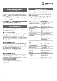
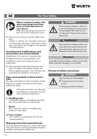
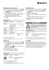
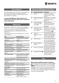
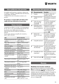
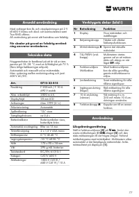
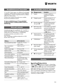
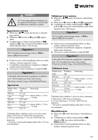
Intended Use
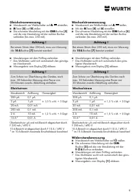
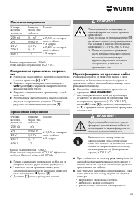
AC and DC voltages from 2 V to 600 V can be
measured; diode and continuity test performed and
true RMS values measured.
Any other use is considered an improper use.
The user is solely responsible for damage
resulting from improper use.
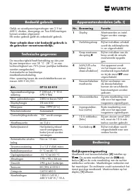
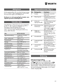
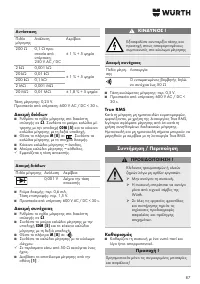
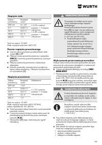
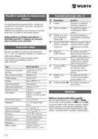
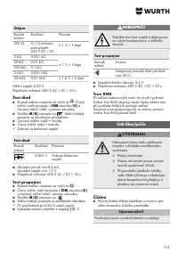
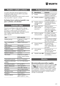
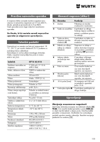
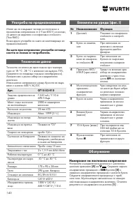
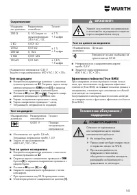
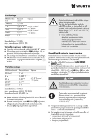
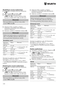
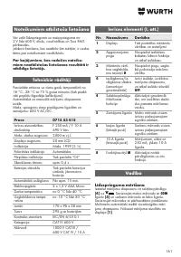
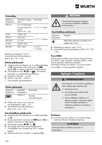
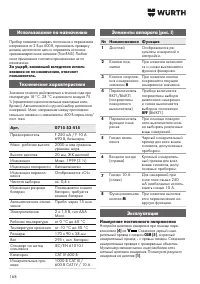
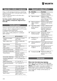
Technical Data
The accuracy values given are for one year at a
temperature of 18 °C - 28 °C and air humidity of
75 % (further annual calibrations are offered).
Automatic and manual measurement range
selection.
Maximum voltage between the connecting sockets
and earth: 600 V AC/DC.
Art.
0715 53 415
Fuse
F 250 mA / F 10 A
690 V fast
Max. operating altitude 2000 m above seal
level
Display height
20 mm LCD
Display
Max 1999 (3 ½)
Polarity indication
Automatic
Overflow display
"OL" is displayed
Sample rate
Approx. 0.4 s.
Battery state
Battery symbol display,
battery change neces
-
sary
Automatic switch-off
After approx. 15 min.
Power supply
2 x 1.5 V type AAA
micro
Operating temperature 0°C to 40°C
Storage temperature
-10°C to 50°C
Dimensions
170 x 90 x 38 mm
Weight
295 g including bat
-
teries
Test standard
IEC/EN 61010-1
Category II:
CAT IV 600 V
Measuring leads
1000 V CAT III /
600 V CAT IV / 10 A
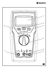
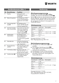
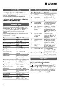
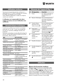
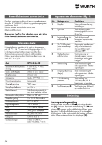
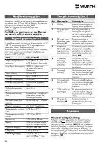
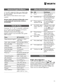
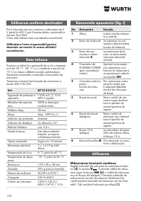
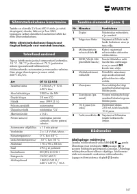
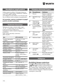
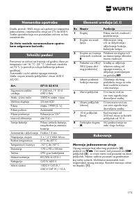
Device elements (Fig. I)
No. Description
Function
1
Display
Measurements and
settings are displayed.
2
Light button
Pressing switches the
torch function on and
off.
3
Hold measure
-
ment button
H
Pressing the button holds
the currently displayed
measured value.
4
ON/OFF switch
(via rotary
switch)
The device is switched
on by selecting a mea
-
suring range and then
switched off again in the
OFF
position.
4
Selector switch
Measuring
function
The various basic
measuring types can be
selected by turning the
rotary switch.
5
Common (earth)
socket
Black measuring lead
for all signal types per
-
mitted for the device.
6
Input socket
(right)
Red measuring lead for
all signal types permit
-
ted for the device.
7
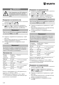
10 A socket (left) For measurements
above 250 mA, the 10
A socket must be used.
8
Mode button
M
Pressing switches the
device to another mode.
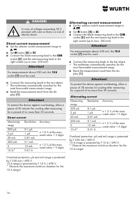
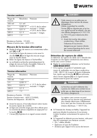
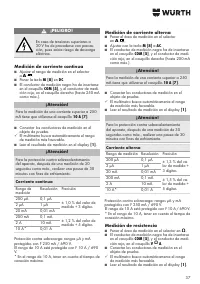
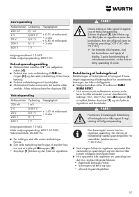
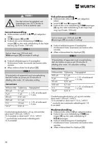
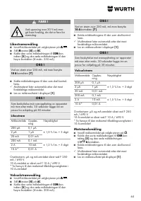
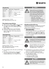
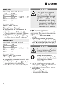
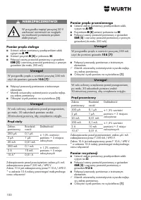
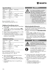
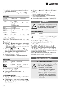
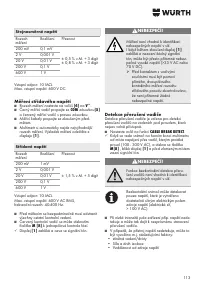
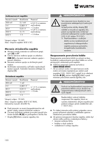
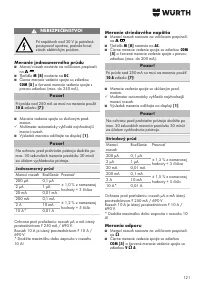
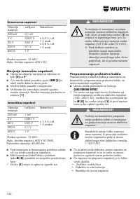
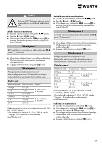
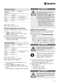
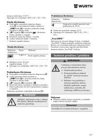
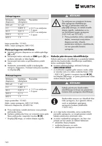
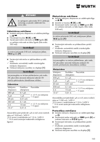
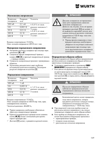
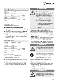
Operation
Direct current measurement
Set the selector switch
[4]
to measurement range
V
. Connect the black measuring lead to the
COM
socket
[5]
and the red measuring lead to the
right socket. Connect the measuring leads to the test
object. The multimeter automatically searches for
the most favourable measurement range. Read the
measurement result from the display
[1]
.
Содержание
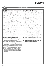
- 167 Используйте только оригинальные; Указания по технике безопасности
- 168 Использование по назначению; За ущерб, возникший вследствие исполь; Технические характеристики; Эксплуатация; Измерение постоянного напряжения
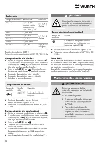
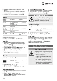
- 169 Определение обрыва кабеля; Измерение переменного напряжения
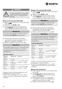
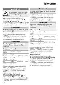
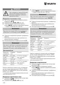
- 170 Измерение постоянного тока; Измерение переменного тока; Измерение сопротивления
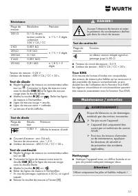
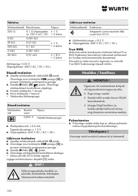
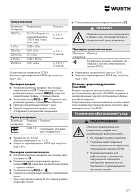
- 171 Сопротивление; Проверка диодов; Проверка целостности цепи; Истинное среднеквадратичное; Техническое обслуживание/уход
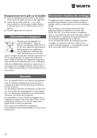
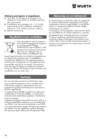
- 172 Очистка; Используйте только указанные батареи и; Замена батарей и предохранителей; Указания по охране окружающей


