
Мультиметры TOPEX 94W102 - инструкция пользователя по применению, эксплуатации и установке на русском языке. Мы надеемся, она поможет вам решить возникшие у вас вопросы при эксплуатации техники.
Если остались вопросы, задайте их в комментариях после инструкции.
"Загружаем инструкцию", означает, что нужно подождать пока файл загрузится и можно будет его читать онлайн. Некоторые инструкции очень большие и время их появления зависит от вашей скорости интернета.


16
TOPEX.PL
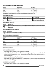
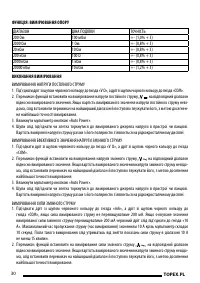
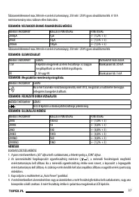
Connect or press test probes to measurement spots of examined circuit or device. When measured resistance is
4.
smaller than approximately 30Ω you will hear characteristic, squeeking sound coming from the in-built beeper.
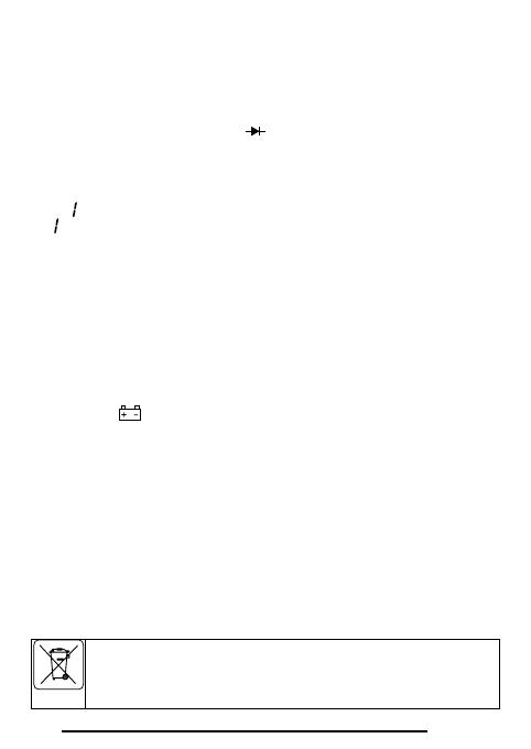
SEMICONDUCTOR DIODE TEST
Connect red test lead to VΩ terminal, black test lead to COM terminal.
1.
Set the dial function selector switch to diode test „
2.
„.
Disconnect power supply from the circuit before testing diode.
3.
Switch on the multimeter with “Auto Power” button.
4.
Connect or press the red test probe to anode of the tested diode, and black test probe to cathode. When voltage
5.
value is displayed on the LCD display (it is diode forward voltage), the diode is not faulty.
When „
6.
„ is shown on the display connect test leads inversely, because the diode might be reverse-biased.
If „
7.
„ is shown after change of polarization, the diode is damaged.
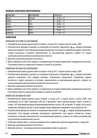
RESISTANCE MEASUREMENT
Connect red test lead to VΩ terminal, black test lead to COM terminal.
1.
Set the dial function selector to resistance measurement “Ω” and correct range corresponding to measured value.
2.
If you do not know range of resistance set the selector switch to maximum range and then reduce it gradually for
the best measurement accuracy.
Switch of the power supply and discharge all capacitors before taking resistance measurement in the device or circuit.
3.
Switch the multimeter with “Auto Power” button.
4.
Connect or press test probes to measurement points of the measured resistance. Read measured resistance value
5.
on the LCD display.
BATTERY REPLACEMENT
When the symbol “
1.
“ appears on the LCD display it indicates that the battery voltage is too low and the battery
should be replaced.
Switch of the multimeter with the “Auto Power” button and disconnect test leads from multimeter terminals.
2.
Unscrew two screws and remove back cover.
3.
Remove old battery, insert new, full 6F22 battery while observing polarity, place the back cover in its place and
4.
ix it with two screws.
FUSE REPLACEMENT
To replace blown fuse switch of the multimeter with the “Auto Power” button, disconnect test leads from multim-
1.
eter terminals, unscrew two screws of the back cover and remove it.
Remove blown fuse, insert new one F250mA/250V, place the back cover in its place and ix it with two screws.
2.
MULTIMETER MAINTENANCE
Wipe body and display screen with soft, dry cloth regularly.
EC DECLARATION OF CONFORMITY
Do not dispose of electrically powered products with household wastes, they should be utilized in proper
plants. Obtain information on wastes utilization from your seller or local authorities. Used up electric and
electronic equipment contains substances active in natural environment. Unrecycled equipment constitutes
a potential risk for environment and human health.
Содержание
- 18 УКАЗАНИЯ ПО ТЕХНИКЕ БЕЗОПАСНОСТИ
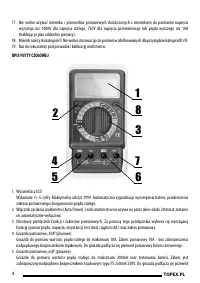
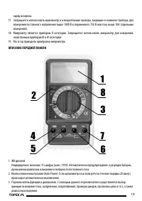
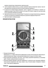
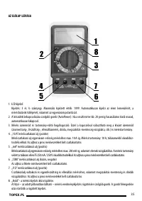
- 19 ОПИСАНИЕ ПЕРЕДНЕЙ ПАНЕЛИ; ЖК дисплей
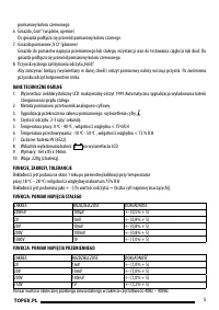
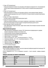
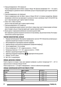
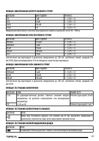
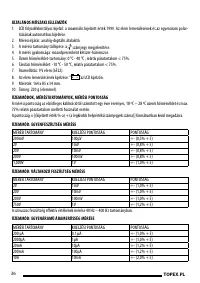
- 20 ОБЩИЕ ТЕХНИЧЕСКИЕ ДАННЫ; Индикация превышения диапазона: цифра „; ФУНКЦИЯ: ИЗМЕРЕНИЕ ПОСТОЯННОГО НАПРЯЖЕНИЯ; ДИАПАЗОН
- 24 ЗАМЕНА БАТАРЕИ; Появление на дисплее значка “; ЗАМЕНА ПРЕДОХРАНИТЕЛЯ; Периодически протирать корпус и дисплей сухой мягкой тряпочкой.


