Материнские платы GIGABYTE GA GC230D rev 1 0 - инструкция пользователя по применению, эксплуатации и установке на русском языке. Мы надеемся, она поможет вам решить возникшие у вас вопросы при эксплуатации техники.
Если остались вопросы, задайте их в комментариях после инструкции.
"Загружаем инструкцию", означает, что нужно подождать пока файл загрузится и можно будет его читать онлайн. Некоторые инструкции очень большие и время их появления зависит от вашей скорости интернета.


Hardware Installation
- 17 -
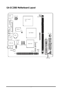
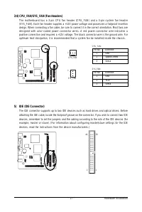
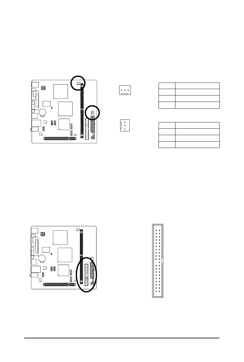
3/4) CPU_FAN/SYS_FAN (Fan Headers)
The motherboard has a 3-pin CPU fan header (CPU_FAN) and a 3-pin system fan header
(SYS_FAN). Each fan header supplies a +12V power voltage and possesses a foolproof insertion
design. When connecting a fan cable, be sure to connect it in the correct orientation. Most fans are
designed with color-coded power connector wires. A red power connector wire indicates a
positive connection and requires a +12V voltage. The black connector wire is the ground wire. For
optimum heat dissipation, it is recommended that a system fan be installed inside the chassis.
Pin No.
Definition
1
GND
2
+12V
3
Sense
SYS_FAN:
1
CPU_FAN
1
SYS_FAN
5) IDE (IDE Connector)
The IDE connector supports up to two IDE devices such as hard drives and optical drives. Before
attaching the IDE cable, locate the foolproof groove on the connector. If you wish to connect two IDE
devices, remember to set the jumpers and the cabling according to the role of the IDE devices (for
example, master or slave). (For information about configuring master/slave settings for the IDE
devices, read the instructions from the device manufacturers.)
1
2
3 9
4 0
Pin No.
Definition
1
GND
2
Speed Control
3
Sense
CPU_FAN:


