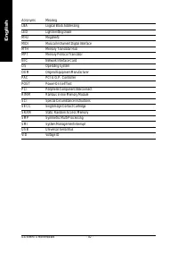
Материнские платы GIGABYTE GA 8IMMT4 - инструкция пользователя по применению, эксплуатации и установке на русском языке. Мы надеемся, она поможет вам решить возникшие у вас вопросы при эксплуатации техники.
Если остались вопросы, задайте их в комментариях после инструкции.
"Загружаем инструкцию", означает, что нужно подождать пока файл загрузится и можно будет его читать онлайн. Некоторые инструкции очень большие и время их появления зависит от вашей скорости интернета.


- 18 -
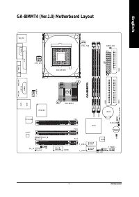
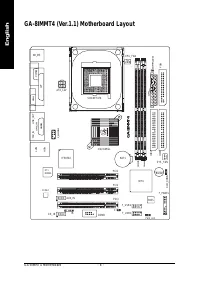
GA-8IMMT4 Motherboard
English
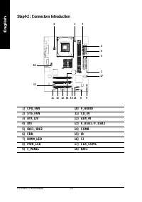
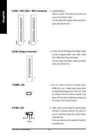
6) FDD (Floppy Connector)
1
5) IDE1 / IDE2 (IDE1 / IDE2 Connector)
8) PWR_LED
7) DIMM_LED
¾
D o n o t r e m o v e m e m o r y m o d u l e s w h i l e
DIMM LED is on. It might cause short or other
unexpected damages due to the 3.3V stand
by voltage. Remove memory modules only
when STR function is disabled by jumper and
AC Power cord is disconnected.
MPD+
MPD-
MPD-
1
+
_
¾
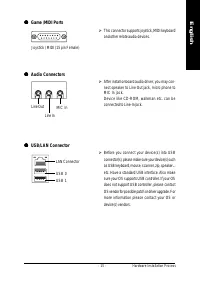
Important Notice:
Please connect first hard disk to IDE1 and
connect CD-ROM to IDE2.
The red stripe of the ribbon cable must be the
same side with the Pin1.
¾
Please connect the floppy drive ribbon cables
to FDD. It supports 360K, 1.2M, 720K, 1.44M
and 2.88M bytes floppy disk types.
The red stripe of the ribbon cable must be the
same side with the Pin1.
¾
PWR_LED is connect with the system power
indicator to indicate whether the system is
on/off. It will blink when the system enters
suspend mode.
If you use dual color LED, power LED will turn
to another color.
IDE2
1
IDE1
1


