Материнские платы GIGABYTE GA 8I915G Pro rev 1 x - инструкция пользователя по применению, эксплуатации и установке на русском языке. Мы надеемся, она поможет вам решить возникшие у вас вопросы при эксплуатации техники.
Если остались вопросы, задайте их в комментариях после инструкции.
"Загружаем инструкцию", означает, что нужно подождать пока файл загрузится и можно будет его читать онлайн. Некоторые инструкции очень большие и время их появления зависит от вашей скорости интернета.

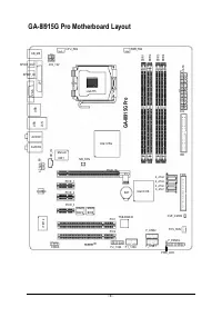


GA-8I915G Pro M otherboard
- 12 -
English
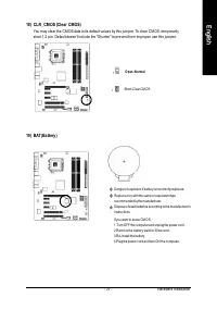
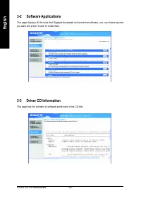
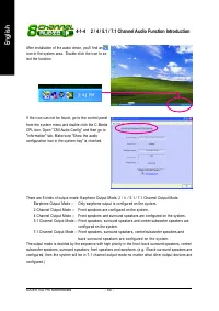
1-3
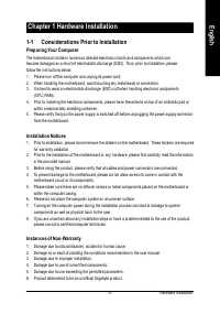
Installation of the CPU and Heatsink
Befor e installing the CPU, plea se com ply with the following conditions:
1. Please m ake su re that the m otherboard sup ports the CPU.
2. Please tak e note of the one indented corner of the CPU. If you install the CPU in the wrong
direction, the CPU will not insert properly. If this occurs, please change the insert direction
of the CPU.
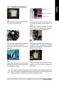
3. Please add an even layer of hea t sink paste between the CPU and hea tsink.
4. Please m a ke sure the heatsink is installed on the CPU prior to system use, otherwise
overheating and perm anent dam age of the CPU m ay occur.
5. Please set the CPU host frequency in accordance with the processor specifications. It is not
recom m ended that the system bus frequency be set beyond hardware specifications since it
does no t m eet the re quired standa rds for the p eripherals. If you wish to set the fr equency
beyond the prop er specifications, please do so according to your hardware specifications
in clu ding the CPU, gr aph ic s c ard , m em ory , h ar d d riv e, etc.
HT fu nct io nal ity re qui rement c ont ent :
Enabling the functionality of Hyper-Threading Technology for your com p uter system requires all
of the following platform com po nents:
- CPU: An In tel
®
Pentiu m 4 Processor with HT Tec hnology
- Chipset: An Intel
®
Chips et that supp orts HT Tech nology
- BIOS: A BIOS that suppor ts HT Tech nology and has it en abled
- OS: An op eration system that ha s optim izations for HT Technology
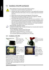
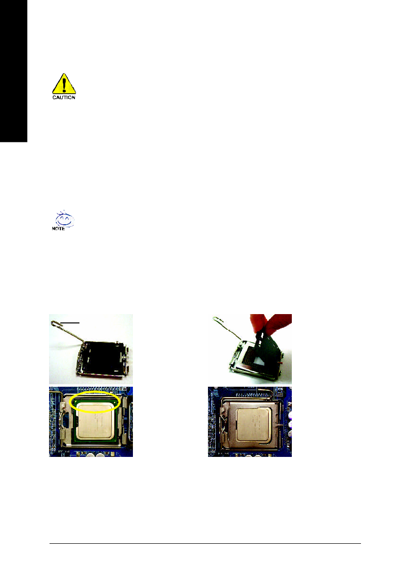
1-3-1 Instal lation of t he CPU
F ig . 1
Ge ntly lift the m etal
le v er lo c ate d o n th e
CPU so ck et to th e
upr ight pos itio n.
M e tal Lev er
F ig . 2
Re m o v e th e p l a s tic
c ov er in g o n th e CPU
s oc k et.
F ig . 3
No tice the sm all go ld
c o lo r e d tr ia n g l e lo -
c ated o n the ed ge o f
t h e C P U s o c k e t .
Align the
F ig . 4
On ce the CPU is
pr ope rly inse rte d,
ple ase replace the
plastic co ver in g a nd
pu sh the m etal lev er
ba ck into its or igin al
po sitio n.
in de nted c or ne r of the CPU with th e tr ia ng le a nd
ge ntly ins er t the CPU into p os ition . ( Gr asp ing the
CPU firm ly b e twee n y ou r thu m b an d for efing er ,
ca re fu lly plac e it in to the s oc ke t in a stra ig ht a nd
d o wn war d s m o tio n. Av o id twis tin g o r be n d in g
m otions that m igh t ca use d am ag e to the CPU d ur-
in g in sta lla tion .)


