
Котел Ferroli DIVATECH с двумя теплообменниками - инструкция пользователя по применению, эксплуатации и установке на русском языке. Мы надеемся, она поможет вам решить возникшие у вас вопросы при эксплуатации техники.
Если остались вопросы, задайте их в комментариях после инструкции.
"Загружаем инструкцию", означает, что нужно подождать пока файл загрузится и можно будет его читать онлайн. Некоторые инструкции очень большие и время их появления зависит от вашей скорости интернета.
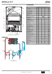
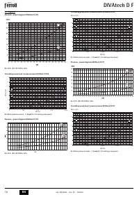
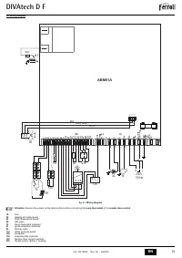


DIVAtech D F
9
EN
cod. 3541P560 - Rev. 00 - 06/2018
Notes:
1.
Parameters with more than one description vary their function and/or range in rela-
tion to the setting of the parameter given in brackets.
2.
Parameters with more than one description are reset to the default value if the pa-
rameter given in brackets is modified.
3.
The Maximum Heating Power parameter can also be modified in Test Mode.
Press the Reset button to return to the Service Menu. Press the Reset button for 20 sec-
onds to exit the card Service Menu, or exiting occurs automatically after 15 minutes.
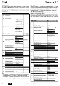
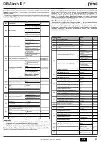
“In” - Information Menu
PAR_INFO
pieces of information are available.
Press the Heating buttons to scroll the list of information in increasing or decreasing or-
der. Press the DHW buttons to display the value.
Notes:
1.
In case of damaged sensor, the card displays hyphens.
Press the Reset button to return to the Service Menu. Press the Reset button for 20 sec-
onds to exit the card Service Menu or exiting occurs automatically after 15 minutes.
"Hi" - History Menu
The card can store the last 11 faults: the History datum item H1: represents the most re-
cent fault that occurred; the History datum item H10: represents the least recent fault that
occurred.
The codes of the faults saved are also displayed in the corresponding menu of the Re-
mote Timer Control.
Press the Heating buttons to scroll the list of faults in increasing or decreasing order.
Press the DHW buttons to display the value.
Press the Reset button to return to the Service Menu. Press the Reset button for 20 sec-
onds to exit the card Service Menu, or exiting occurs automatically after 15 minutes.
"rE" - History Reset
Press the Eco/Comfort button for 3 seconds to delete all the faults stored in the History
Menu: the card will automatically exit the Service Menu, in order to confirm the operation.
Press the Reset button for 20 seconds to exit the card Service Menu, or exiting occurs
automatically after 15 minutes.
4.2 Commissioning
Before lighting the boiler
•
Check the seal of the gas system.
•
Check correct prefilling of the expansion tank.
•
Fill the water system and make sure all air contained in the boiler and the system
has been vented.
•
Make sure there are no water leaks in the system, DHW circuits, connections or boiler.
•
Check correct connection of the electrical system and efficiency of the earthing system.
•
Make sure the gas pressure for heating is that required.
•
Make sure there are no flammable liquids or materials in the immediate vicinity of
the boiler
B
IF THE ABOVE INSTRUCTIONS ARE NOT OBSERVED THERE MAY BE
RISK OF SUFFOCATION OR POISONING DUE TO GAS OR FUMES ES-
CAPING; DANGER OF FIRE OR EXPLOSION. ALSO, THERE MAY BE A
RISK OF ELECTRIC SHOCK OR FLOODING THE ROOM.
Checks during operation
•
Switch the unit on.
•
Check the tightness of the fuel circuit and water systems.
•
Check the efficiency of the flue and air/fume ducts while the boiler is working.
•
Make sure the water is circulating properly between the boiler and the systems.
•
Make sure the gas valve modulates correctly in the heating and domestic hot water
production stages.
•
Check correct boiler lighting by performing various tests, turning it on and off with
the room thermostat or remote control.
•
Make sure the fuel consumption indicated on the meter matches that given in the
technical data table in cap. 5.
•
Make sure that with no demand for heating, the burner lights correctly on opening a
hot water tap. Check that in heating mode, on opening a hot water tap, the heating
circulating pump stops and there is regular production of hot water.
•
Make sure the parameters are programmed correctly and carry out any required
customisation (compensation curve, power, temperatures, etc.).
4.3 Maintenance
IMPORTANT
B
ALL MAINTENANCE WORK AND REPLACEMENTS MUST BE CARRIED
OUT BY SKILLED QUALIFIED PERSONNEL.
Before carrying out any operation inside the boiler, disconnect the power
and close the gas cock upstream. Otherwise there may be a danger of ex-
plosion, electric shock, suffocation or poisoning.
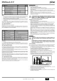
Periodical inspection
To ensure proper operation of the unit over time, have qualified personnel carry out a
yearly inspection, providing for the following checks:
•
The control and safety devices (gas valve, flow switch, thermostats, etc.) must func-
tion correctly.
•
The fume exhaust circuit must be perfectly efficient.
(Sealed chamber boiler: fan, pressure switch, etc. - The sealed chamber must be
tight: seals, cable glands, etc.)
(Open chamber boiler: anti-backflow device, fume thermostat, etc.)
•
The air/fume terminal and ducts must be free of obstructions and leaks
•
The burner and exchanger must be clean and free of deposits. Do not use chemical
products or wire brushes to clean.
•
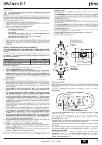
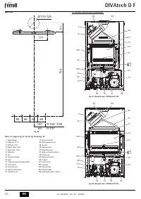
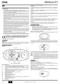
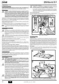
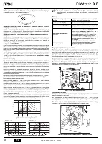
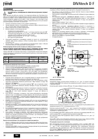
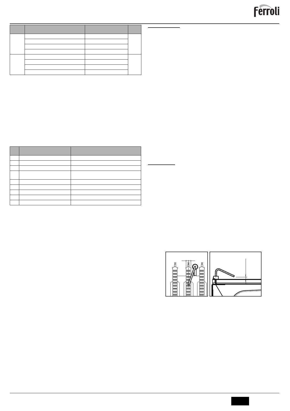
The electrode must be properly positioned and free of deposits.
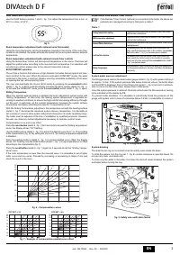
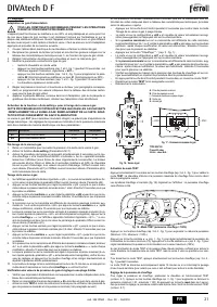
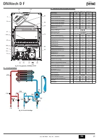
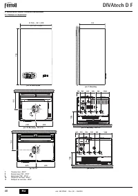
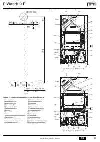
fig. 19 - Electrode positioning
•
The gas and water systems must be tight.
•
The pressure of the water in the system when cold must be approx. 1 bar; otherwise,
bring it to that value.
•
The circulating pump must not be blocked.
•
The expansion tank must be filled.
•
The gas flow and pressure must match that given in the respective tables.
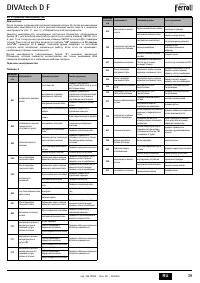
P20
Solar ignition temperature (b02=1)
0÷20°C
10
Solar ignition temperature (b02=2)
0÷20°C
No effect on adjustment (b02=3)
--
No effect on adjustment (b02=4)
--
P21
Solar standby time (b02=1)
0-20 seconds
10
Solar standby time (b02=2)
0-20 seconds
No effect on adjustment (b02=3)
--
No effect on adjustment (b02=4)
--
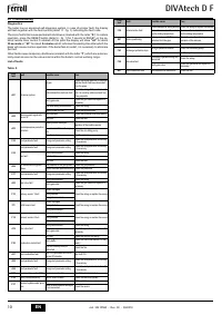
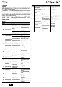
Con-
tents
Description
Range
t01
NTC Heating sensor (°C)
between 05 and 125°C
t02
NTC Safety sensor (°C)
between 05 and 125°C
t03
NTC DHW sensor (°C)
between 05 and 125°C
t04
NTC External sensor (°C)
between -30 and 70°C (negative values flash)Without NTC =
--
L05
Actual burner power (%)
00%=Min., 100%=Max.
F06
Actual Flame resistance (kOhm)
00-99 kOhm (-- = burner off)
St07
Fan step (Number)
0=Off, 1=Min, 2=Med, 3=Max
F08
Actual DHW drawing (L min/10)
L min/10 over 99 flashing 3 figures
PP09
Actual modulating pump speed (%)
00-100% not working in this model
Contents Description
Range
DIVAtech
D F
3
±
0,5
=
=

