
Котел Ferroli DIVATECH с двумя теплообменниками - инструкция пользователя по применению, эксплуатации и установке на русском языке. Мы надеемся, она поможет вам решить возникшие у вас вопросы при эксплуатации техники.
Если остались вопросы, задайте их в комментариях после инструкции.
"Загружаем инструкцию", означает, что нужно подождать пока файл загрузится и можно будет его читать онлайн. Некоторые инструкции очень большие и время их появления зависит от вашей скорости интернета.
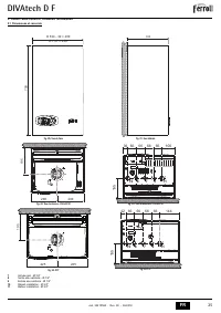
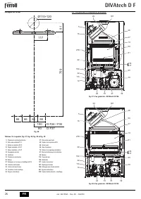
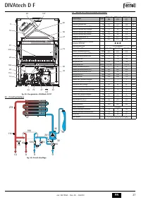
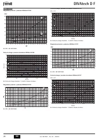
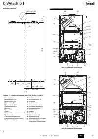


DIVAtech D F
7
EN
cod. 3541P560 - Rev. 00 - 06/2018
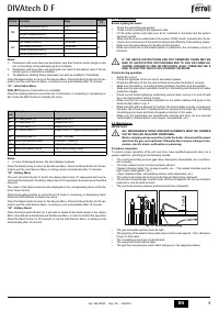
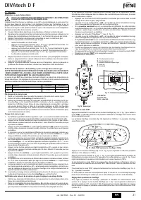
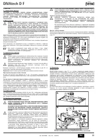
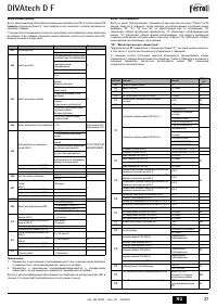
4.1 Adjustments
Gas conversion
B
ALL COMPONENTS DAMAGED DURING CONVERSION OPERATIONS
MUST BE REPLACED
.
The unit can operate on natural gas or LPG and is factory-set for use with one of these
two gases, as clearly shown on the packing and on the data plate. Whenever a gas dif-
ferent from that for which the unit is arranged has to be used, the special conversion kit
will be required, proceeding as follows:
1.
Disconnect the boiler power supply and close the gas cock.
2.
Replace the nozzles at the main burner, fitting the nozzles specified in the technical
data table in cap. 5, according to the type of gas used
3.
Switch the boiler power on and open the gas cock.
4.
Modify the parameter for the type of gas:
•
put the boiler in standby mode
•
press the DHW buttons details 1 and 2 - fig. 1 for 10 seconds: the display shows
“
b01
“ flashing.
•
press the DHW buttons details 1 and 2 - fig. 1 to set the parameter
00
(for nat-
ural gas operation) or
01
(for LPG operation).
•
press the DHW buttons details 1 and 2 - fig. 1 for 10 seconds.
•
the boiler will return to standby mode
5.
Adjust the minimum and maximum pressures at the burner (ref. relevant para-
graph), setting the values given in the technical data table for the type of gas used
6.
Apply the sticker contained in the conversion kit, near the data plate as proof of the
conversion.
Activation of Auto-setting function for gas valve calibration
THIS PROCEDURE MUST ONLY BE CARRIED OUT IN THE FOLLOWING CASES:
GAS VALVE REPLACEMENT, CARD REPLACEMENT, CONVERSION FOR GAS
CHANGE
.
The B&P Gas Valve (with integrated modulating operator) does not provide for mechan-
ical calibration: the minimum and maximum power adjustments are therefore electroni-
cally done via two parameters:
Gas valve pre-calibration
1.
Connect a pressure gauge to monitor the gas valve outlet pressure.
2.
Enable the
Auto-setting
function (Parameter b12=1).
3.
Activate the calibration procedure by pressing the heating + button and Eco/Comfort
button together for 5 seconds. The message "Au-to" immediately appears (in two
successive flashes) and the burner is lit. Within 8 seconds (natural gas and LPG)
the boiler finds the ignition point. The ignition point, absolute minimum current Offset
(Parameter q01) and absolute maximum current Offset (Parameter q02) values are
stored by the card.
Gas valve calibration
1.
The display will show "q02" flashing; the modulation current is forced to the pre-cal-
ibration value of the absolute maximum current Offset parameter (Parameter q02).
2.
Press the DHW buttons to adjust the parameter "q02" until the maximum nominal
pressure minus 1mbar is reached on the pressure gauge. Wait 10 seconds for the
pressure to stabilise.
3.
Press the
DHW “+”
button to set the parameter
“q02”
until the maximum nominal
pressure is reached on the pressure gauge. Wait 10 seconds for the pressure to sta-
bilise.
4.
If the pressure read on the pressure gauge is different from the maximum nominal pres-
sure, proceed in increments of 1 or 2 units of the parameter "q02" by pressing the
DHW
“+”
button: after each change, wait 10 seconds for the pressure to stabilise.
5.
When the pressure read on the pressure gauge is equal to the maximum nominal
pressure (the newly calibrated value of the parameter "q02" is automatically saved),
press the
heating “–”
button: the display will show "q01" flashing; the modulation
current is forced to the pre-calibration value of the absolute minimum current Offset
parameter (Parameter q01).
6.
Press the DHW buttons to adjust the parameter "q01" until the minimum nominal
pressure plus 0.5mbar is reached on the pressure gauge. Wait 10 seconds for the
pressure to stabilise.
7.
Press the
DHW “-”
button to adjust the parameter "q01" until the minimum nominal pres-
sure is reached on the pressure gauge. Wait 10 seconds for the pressure to stabilise.
8.
If the pressure read on the pressure gauge is different from the minimum nominal
pressure, proceed in decrements of 1 or 2 units of the parameter
“q01”
by pressing
the
DHW “-”
button: after each change, wait 10 seconds for the pressure to stabilise.
9.
When the pressure read on the pressure gauge is equal to the minimum nominal
pressure (the newly calibrated value of the parameter "q01" is automatically saved.),
recheck both adjustments by pressing the heating buttons and correct them if nec-
essary by repeating the procedure described above.
10. The calibration procedure ends automatically after 15 minutes or by pressing the
heating “+”
and Eco/Comfort buttons together for 5 seconds.
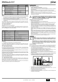
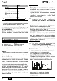
Checking of gas pressure values and adjustment with limited range
•
Check that the supply pressure complies with that indicated in the technical data table.
•
Connect a suitable pressure gauge to the pressure sampling point
“B”
located
downstream from the gas valve.
•
Activate the
TEST
mode and follow the instructions for checking the gas pressures
at maximum power and minimum power (see next par.).
If the maximum and/or minimum nominal pressures read on the pressure gauge are dif-
ferent from those indicated in the technical data table, proceed with the next sequence.
•
Press the Eco/Comfort button for 2 seconds to go to the gas valve Calibration with
limited range mode.
•
The card goes to the setting
“q02”
; displaying the currently saved value by pressing
the DHW buttons.
•
If the
maximum pressure
read on the pressure gauge is different from the nominal
one, proceed in increments/decrements of 1 or 2 units of the parameter
“q02”
by
pressing the DHW buttons: after each change, the value is stored; wait 10 seconds
for the pressure to stabilise.
•
Press the heating “-” button (ref. 3 - fig. 1).
•
The card goes to the setting
“q01”
; displaying the currently saved value by pressing
the DHW buttons.
•
If the
minimum pressure
read on the pressure gauge is different from the nominal
one, proceed in increments/decrements of 1 or 2 units of the parameter
“q01”
by
pressing the DHW buttons: after each change, the value is stored; wait 10 seconds
for the pressure to stabilise.
•
Recheck both settings by pressing the heating buttons and if necessary correct
them by repeating the procedure described above.
•
Pressing the Eco/Comfort button for 2 seconds returns to TEST mode.
•
Deactivate
TEST
mode (see next par.).
•
Disconnect the pressure gauge.
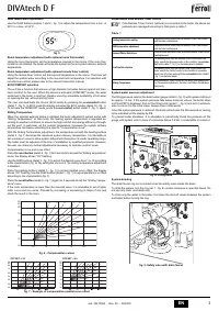
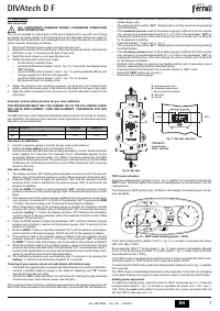
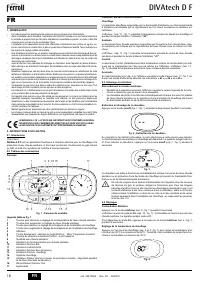
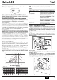
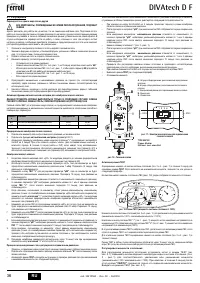
TEST mode activation
Press the heating buttons (details 3 and 4 - fig. 1) together for 5 seconds to activate the
TEST
mode. The boiler lights at the maximum heating power set as described in the fol-
lowing section.
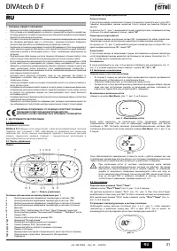
The heating and DHW symbols (fig. 18) flash on the display; the heating power will ap-
pear alongside.
fig. 18 - TEST mode (heating power = 100%)
Press the heating buttons (details 3 and 4 - fig. 1) to increase or decrease the power
(Min.=0%, Max.=100%).
By pressing the DHW
“-”
button (detail 1 - fig. 1), boiler output is immediately adjusted
to min. (0%). By pressing the DHW
“+”
button (detail 2 - fig. 1), boiler output is immedi-
ately adjusted to max. (100%).
If the TEST mode is activated and enough hot water is drawn to activate the DHW mode,
the boiler remains in TEST mode but the 3-way valve goes to DHW.
To deactivate the TEST mode, press the heating buttons (details 3 and 4 - fig. 1) together
for 5 seconds.
The TEST mode is automatically deactivated in any case after 15 minutes or on stopping
of hot water drawing (if enough hot water has been drawn to activate the DHW mode).
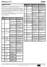
Heating power adjustment
To adjust the heating power, switch the boiler to TEST mode (see sec. 4.1). Press the
heating buttons detail 3 - fig. 1 to increase or decrease the power (min. = 00 - max. =
100). Press the
reset
button within 5 seconds and the max. power will remain that just
set. Exit TEST mode (see sec. 4.1).
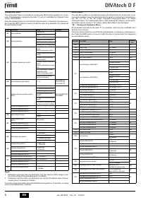
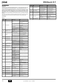
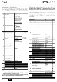
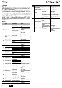
Contents Description
Natural Gas
Propane Gas
q01
Absolute minimum current offset
0÷100
0÷150
q02
Absolute maximum current offset
0÷100
0-150
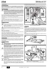
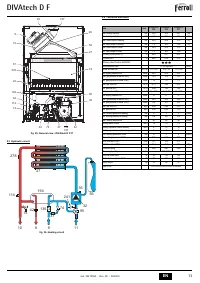
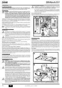
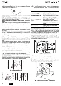
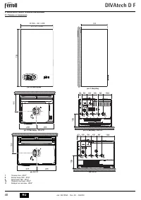
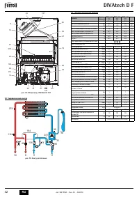
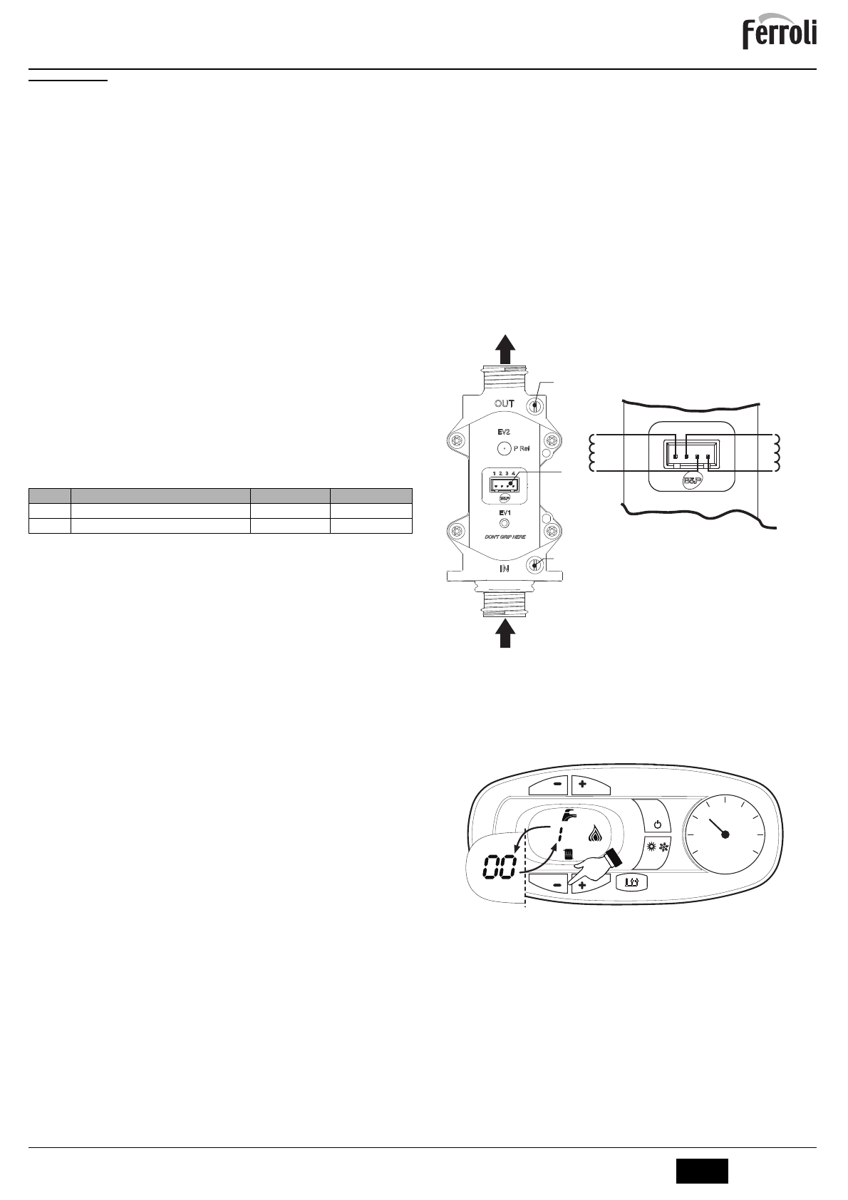
fig. 16 - Gas valve
A
- Upstream pressure point
B
- Downstream pressure point
I
- Gas valve electrical connection
R
- Gas outlet
S
- Gas inlet
fig. 17 - Gas valve connection
TYPE SGV100
Pi max 65 mbar
24 Vdc - class B+A
R
B
I
A
S
~ 65
W
~ 24
W
1 2 3 4
0
1
4
2
3
reset
eco
comfort
II
II
I I
I I
I I I I I I
II
II
II
II
II
II
I I
I I
I I I I I I
II
II
II
II

