
Котел Ferroli DIVATECH с двумя теплообменниками - инструкция пользователя по применению, эксплуатации и установке на русском языке. Мы надеемся, она поможет вам решить возникшие у вас вопросы при эксплуатации техники.
Если остались вопросы, задайте их в комментариях после инструкции.
"Загружаем инструкцию", означает, что нужно подождать пока файл загрузится и можно будет его читать онлайн. Некоторые инструкции очень большие и время их появления зависит от вашей скорости интернета.


DIVAtech D F
5
EN
cod. 3541P560 - Rev. 00 - 06/2018
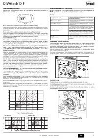
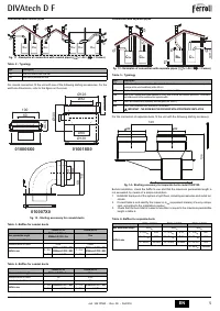
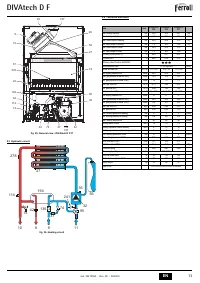
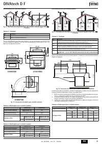
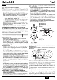
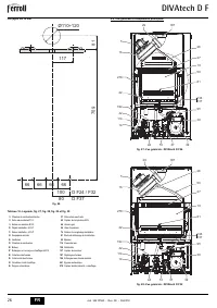
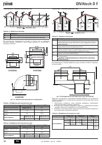
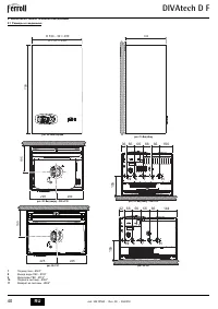
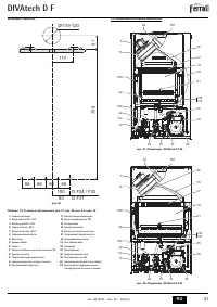
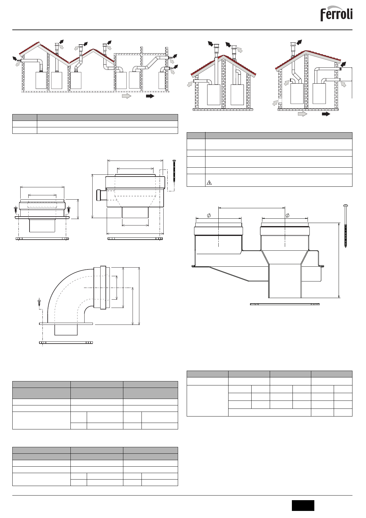
Connection with coaxial pipes
fig. 11 - Examples of connection with coaxial pipes (
= Air /
= Fumes)
Table. 2 - Typology
For coaxial connection, fit the unit with one of the following starting accessories. For the
wall hole dimensions, refer to the figure on the cover.
fig. 12 - Starting accessory for coaxial ducts
Table. 3- Baffles for coaxial ducts
Table. 4- Baffles for coaxial ducts
Connection with separate pipes
fig. 13 - Examples of connection with separate pipes (
= Air /
= Fumes)
Table. 5 - Typology
For the connection of separate ducts, fit the unit with the following starting accessory:
fig. 14 - Starting accessory for separate ducts code 010031X0
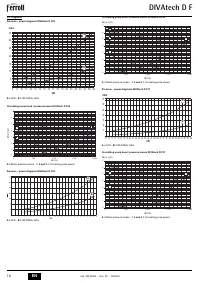
Before installation, check the baffle to use and that the maximum permissible length is
not exceeded, by means of a simple calculation:
1.
Establish the layout of the system of split flues, including accessories and outlet ter-
minals.
2.
Consult table 6 and identify the losses in m
eq
(equivalent meters) of every compo-
nent, according to the installation position.
3.
Check that the sum total of losses is less than or equal to the maximum permissible
length in table 6.
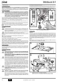
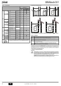
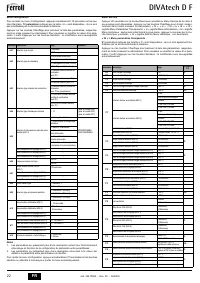
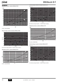
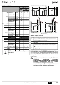
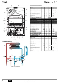
Table. 6- Baffles for separate ducts
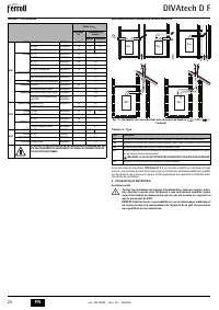
Type
Description
C1X
Wall horizontal exhaust and inlet
C3X
Roof vertical exhaust and inlet
Coaxial 60/100
Coaxial 80/125
Max. permissible length
DIVAtech D F24 = 5 m
DIVAtech D F32 = 5 m
10 m
Reduction factor 90° bend
1 m
0.5 m
Reduction factor 45° bend
0.5 m
0.25 m
Baffle to use
0 ÷ 2 m
DIVAtech D F24 = Ø43
DIVAtech D F32 = Ø45
0 ÷ 3 m
DIVAtech D F24 = Ø43
DIVAtech D F32 = Ø45
2 ÷ 5 m
no baffle
3 ÷ 10 m
no baffle
Coaxial 60/100
Coaxial 80/125
Max. permissible length
DIVAtech D F37 = 4 m
10 m
Reduction factor 90° bend
1 m
0.5 m
Reduction factor 45° bend
0.5 m
0.25 m
Baffle to use
0 ÷ 2 m
DIVAtech D F37 = Ø50
0 ÷ 3 m
DIVAtech D F37 = Ø50
2 ÷ 4 m
no baffle
3 ÷ 10 m
no baffle
C
1X
C
1X
C
3X
C
3X
C
3X
C
1X
Ø126
Ø82
Ø60
Ø130
Ø
100
010018X0
010006X0
100
60
45.6
010007X0
68
11
8
100
60
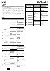
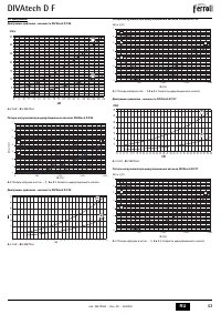
Type
Description
C1X
Wall horizontal exhaust and intake. The inlet/outlet terminals must be concentric or close enough to be
undergo similar wind conditions (within 50 cm)
C3X
Roof vertical exhaust and intake. Inlet/outlet terminals like for C12
C5X
Wall or roof exhaust and intake separate or in any case in areas with different pressures. The exhaust
and intake must not be positioned on opposite walls.
C6X
Intake and exhaust with separately certified pipes (EN 1856/1)
B2X
Intake from installation room and wall or roof exhaust
IMPORTANT - THE ROOM MUST BE PROVIDED WITH APPROPRIATE VENTILATION
DIVAtech D F24
DIVAtech D F32
DIVAtech D F37
Max. permissible length
60 m
eq
48 m
eq
40 m
eq
Baffle to use
0 - 20 m
eq
Ø 43
0 - 15 m
eq
Ø 45
0 - 10 m
eq
Ø 47
20 - 45 m
eq
Ø 47
15 - 35 m
eq
Ø 50
10 - 20 m
eq
Ø 50
45 - 60 m
eq
No baffle
35 - 48 m
eq
No baffle
20 - 30 m
eq
Ø 52
30 - 40 m
eq
No baffle
C
5x
C
3x
B
2x
C
1x
max 50 cm
120
82
136
82

