Кондиционеры Daikin FAQ-C9 - инструкция пользователя по применению, эксплуатации и установке на русском языке. Мы надеемся, она поможет вам решить возникшие у вас вопросы при эксплуатации техники.
Если остались вопросы, задайте их в комментариях после инструкции.
"Загружаем инструкцию", означает, что нужно подождать пока файл загрузится и можно будет его читать онлайн. Некоторые инструкции очень большие и время их появления зависит от вашей скорости интернета.
6
English
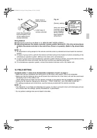
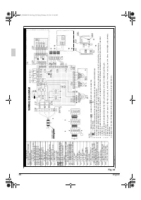
(2) Investigate whether the installation location (such as the floor and wall) can bear the weight of the
unit and, if necessary, reinforce the location with such as boards and beams before installation. To
avoid vibration and abnormal noise, reinforce the location before installation.
(3) The indoor unit may not be directly installed on the wall. Use the attached installation panel (1)
before installing the unit.
4. PREPARATION BEFORE INSTALLATION
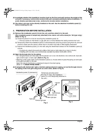
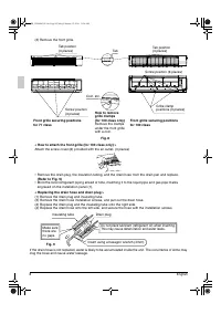
(1) Remove the installation panel (1) from the unit, and then attach it to the wall.
(The installation panel is temporarily attached to the indoor unit with screws (for 100 type only).)
(Refer to Fig. 3)
(a) Check the place for a hole for securing the installation panel (1).
•
Choose a place so that there is a gap (50 mm or more) between the ceiling and the main unit.
(b) Temporarily attach the installation panel (1) at the temporary-securing position using the hole, and use
a level to make sure the panel is either level or its drain hose side is tilted slightly downward.
(c) Secure the installation panel (1) to the wall using the attachment screws for the installation panel (2)
or bolts.
•
If using bolts, attach the panel with a M8 or M10 bolt on both sides (for a total of 2 bolts).
•
If dealing with concrete, use commercially available foundation bolts (M8 or M10).
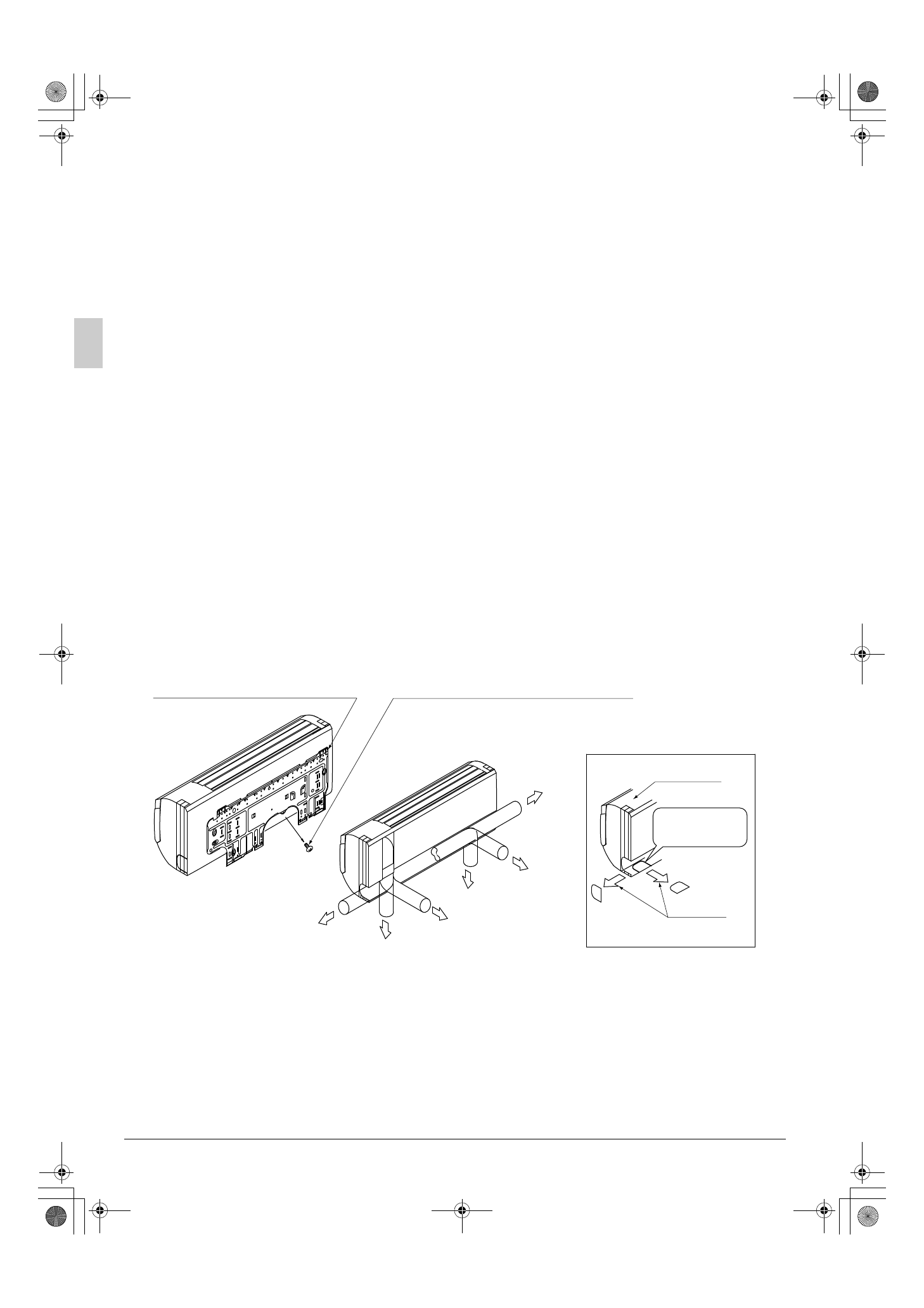
(2) Open the through-hole for the piping.
•
The refrigerant pipe and drain pipe can be passed out in one of 6 directions: left, bottom-left, back-left,
right, bottom-right, or back-right.
(Refer to Fig. 4)
•
Referring to the punch mark on the installation panel (1), choose where to pass the piping out and open
a through-hole (
φ
80) in the wall.
Open the hole so that there is a downward slope for the drain piping.
(Refer to “
7. DRAIN PIPING WORK
”.)
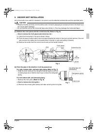
(3) If using the left, bottom-left, right, or bottom-right positions for piping, cut out the through-hole for
the piping in the front grill using such as a box cutter. (Refer to Fig. 5)
Right pipe
Left pipe
Back-left pipe
Back-right pipe
Bottom-left pipe
Bottom-right pipe
Front grille
Fig. 3
Fig. 4
Fig. 5
Installation panel (1) (accessory)
Temporary-securing screw
(For the 71 class, the installation
panel (1) is not temporarily attached to
the unit.)
Cut out along
the groove.
Cut away
01_EN_3P184443-9U.fm Page 6 Friday, February 12, 2016 11:24 AM


